- Details
- Hits: 416
There are a number of different PLL synthesiser chips available from different vendors that are useful in the design of beacon transmitters. FSK modulation is conveniently generated by continuously re-programming the frequency registers with data from a micro-controller. There are downsides to this apparent simplicity. Firstly phase noise (PN) and secondly key-clicks can be at unacceptably high levels.
PN can be minimised by careful decoupling and filtering of power supplies [1] and choice of suitably high reference frequency. A more tricky issue can be the key-clicks arising from the FSK keying process. These arise from various auto-calibration and initialisation processes that are triggered within the chips when the frequency is changed by register updates. The data sheets give few details of these as they are probably proprietary. An exception to this the ADF5355/6 and ADF4355/6 series for chips from Analog Devices which allow a designer some control of the over the auto-cal process which is largely responsible for the key-clicks.
In the AD5355 [2] the auto-calibration is controlled by bit 21 in Register 0. When bit 21 is set to 1 the auto-calibration is on and when 0 it is off. As auto-calibration is required for the correct operation of the chip it needs to be activated periodically. Also Reg 0 is used to do frequency updates by latching loaded data in from registers 1 and 2, so it must be loaded for every frequency shift. A solution to this is that, at the start of every keying cycle, a full initialisation is performed by loading every register as described in the datasheet and then frequency updates are performed by only loading Registers 2, 1 and 0 and twiddling bit 21 of Reg 0 to 0 during the keying cycle. If periodic full initialisations are not done loss of lock will eventually occur due to either temperature drift or transient disturbances. On page 22 of Rev.D of the datasheet it is stated that is is possible to "Disable the automatic calibration only for fixed frequency applications, phase adjust applications, or very small (<10 kHz) frequency jumps". As the present application involves small frequency excursions for FSK keying this is feasible.
This keying scheme has been implemented in the code for the GB3RMK 50 MHz synchronous beacon near Inverness, which uses Bo, OZ2M’s PI4ino code [3], modified to do the timed frequency hopping running on an Arduino pro-mini. Figure 1 shows the effect of key-clicks and figure 2 shows the same plot with the Register 0, 1 and 2 being loaded with bit 21 of register 0 set to 0. The same keying scheme has been found effective at 10 GHz.
The modified ADF5355.cpp file for the PI4ino code is available on Github [4].
Finally before anybody else comments the ADF5355 does operate below 54 MHz, I was prepared to add a divide by two stage on its output for 50 MHz operation but did not find in necessary. Maybe I was lucky!
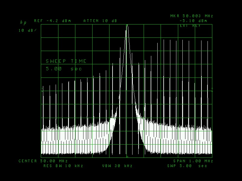
Figure 1 keying cycle showing the effect of key-clicks
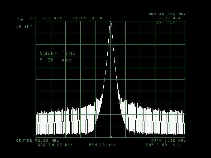
Figure 2 Keying cycle with only registers 2,1 and 0 loaded with bit 21 of register 0 set to 0.
References
- https://gm8bjf.joomla.com/past-talks/15-reducing-phase-noise-pn-on-chinese-adf5355-boards
- https://www.analog.com/media/en/technical-documentation/data-sheets/ADF5355.pdf
- Bo, OZ2M PI4ino
- https://github.com/gm8bjf/ADF5355.cpp/blob/main/ADF5355.cpp
- Details
- Hits: 1709
Over the course of the last year I have building up a remote station primarily for VHF and have arranged that a 2m Yagi can be rotated remotely. For this I used the excellent K3NG arduino rotator control software as described here. To point the Yagi I used the CDE AR40 rotator which was already installed. This has two windings, one to turn clockwise and one for anti-clockwise. To make the rotator rotate one or other winding is energised by a pair of relays.
For this I used one of the two-relay modules which are widely available on Ebay and similar sites which is shown below. These are nicely constructed on a glass fibre PCB and include an opto-isolator to protect and isolate the Anduino from the load circuit. The rotator draws about 4 A when turning and the rating on the relay casing suggests it can handle 15A when switching 125 VAC so the module seemed to be conservatively rated for this application.
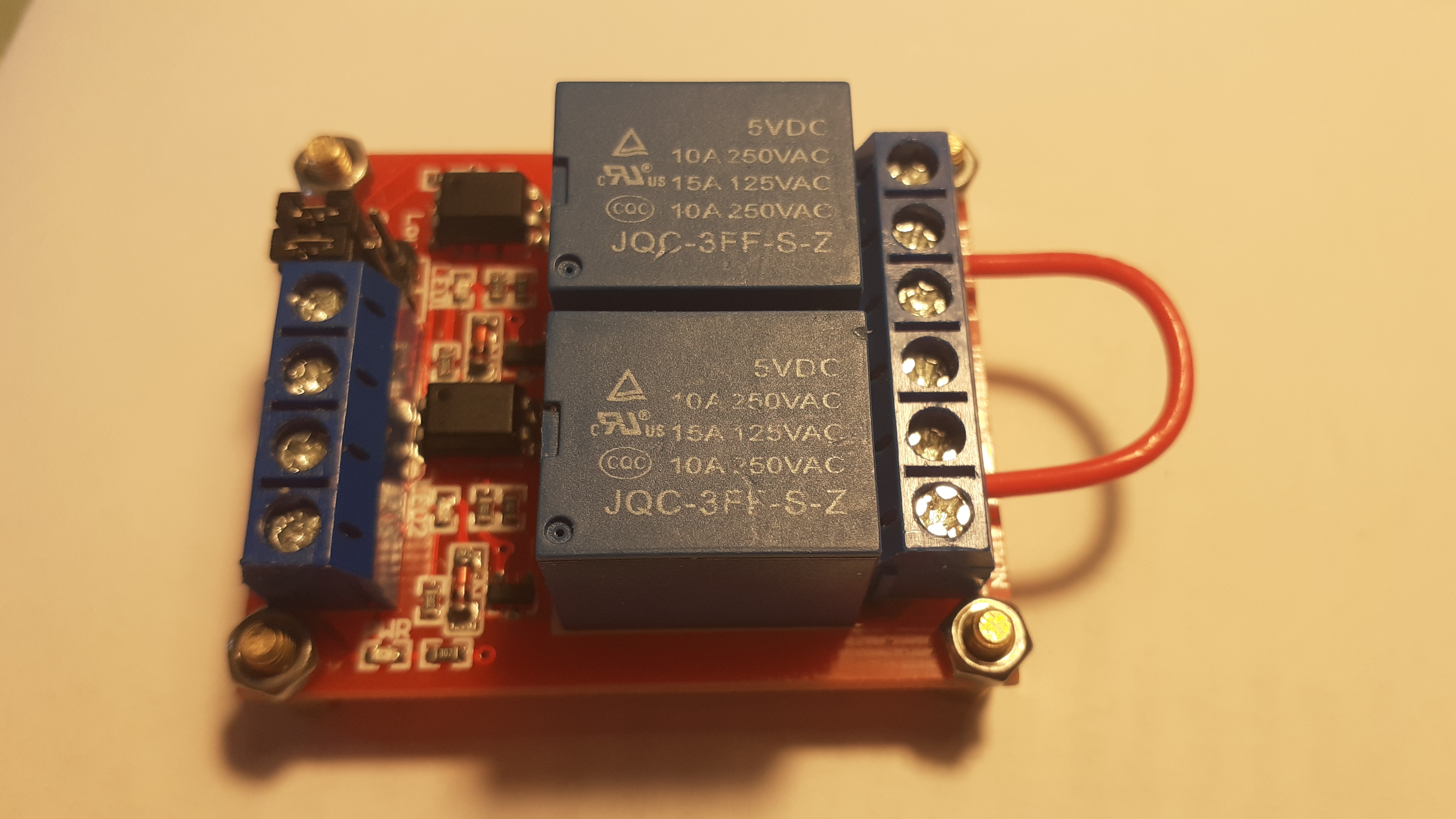
This module worked fine for around 3 months but started to show problems after the proper CDE motor start/run capacitor was fitted. The issue was that the contacts started to stick (weld!) together in the "on" position when the relays were operated. Eventually both contacts welded in the "on" position keeping both forward and reverse windings simultaneously energised. Initially I did not realise this had happened and the result was that the toroidal mains transformer I was using to supply around 20 Vac to the rotator failed when its primary went open circuit. Needless to say this happened when I was at the remote end of the link. On the next visit to the remote site I was able to diagnose the fault when I found that both sets of contact were stuck closed which was alarming.
Fortunately the good old CDE rotator seems to have survived.
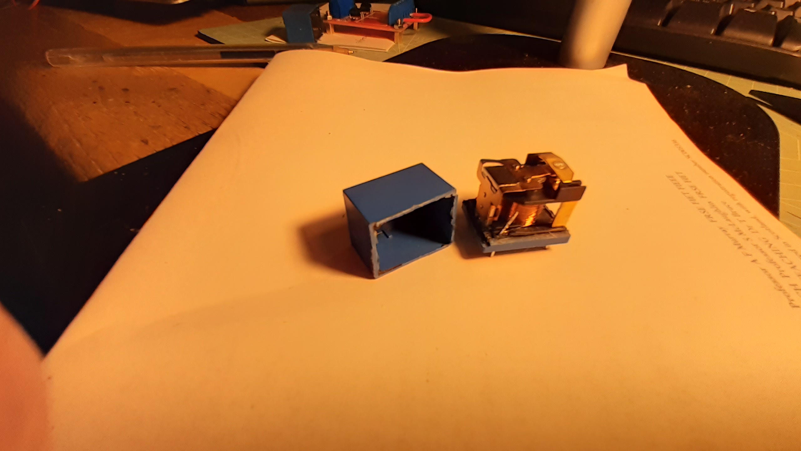
I removed the module from the unit and in the process of moving it about the contacts freed themselves. As I had already had another of these relays fail in another project I opened one of them by carefully cutting off the case with a Dremel-type tool. On initial inspection the contacts look quite substantial being about 4mm in diameter.
Closer inspection of the contacts was carried out by bending the top one and the movable contact out of the way and the bottom contact was seen to be badly pitted and burnt looking as shown below.
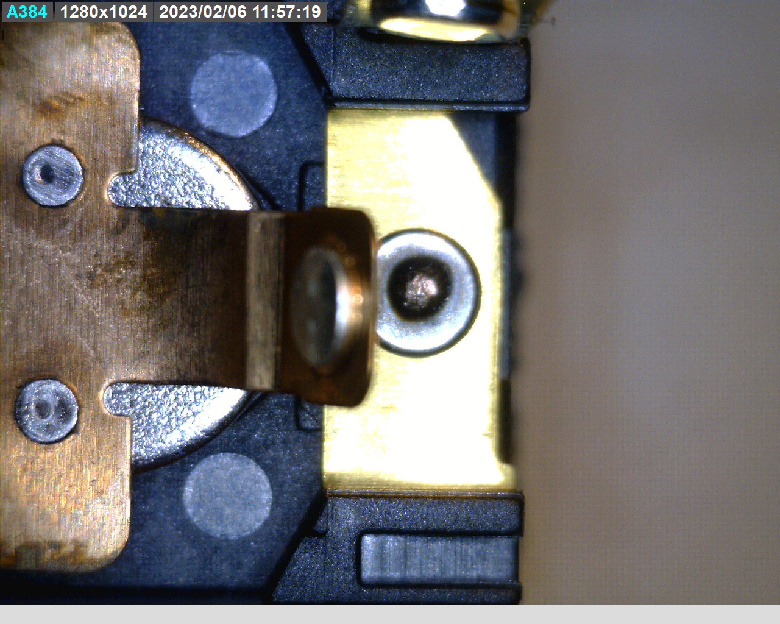
Clearly the ratings printed on the case are considerably over-stated and while the physical size of the contact looks adequate they are made of some inferior material. One can only assume that the relay designers have, whether for reasons of cost or ignorance, got the metallurgy of the contacts wrong! Good quality relays normally use some refractory metal for the contact which resists this kind of damage and failure.
The relays in my unit are not marked with a makers name or trademark but on further research on the internet I read that even ones that show a manufacturers markings such as Songle and Tong Ling exhibit the same failings as described here.
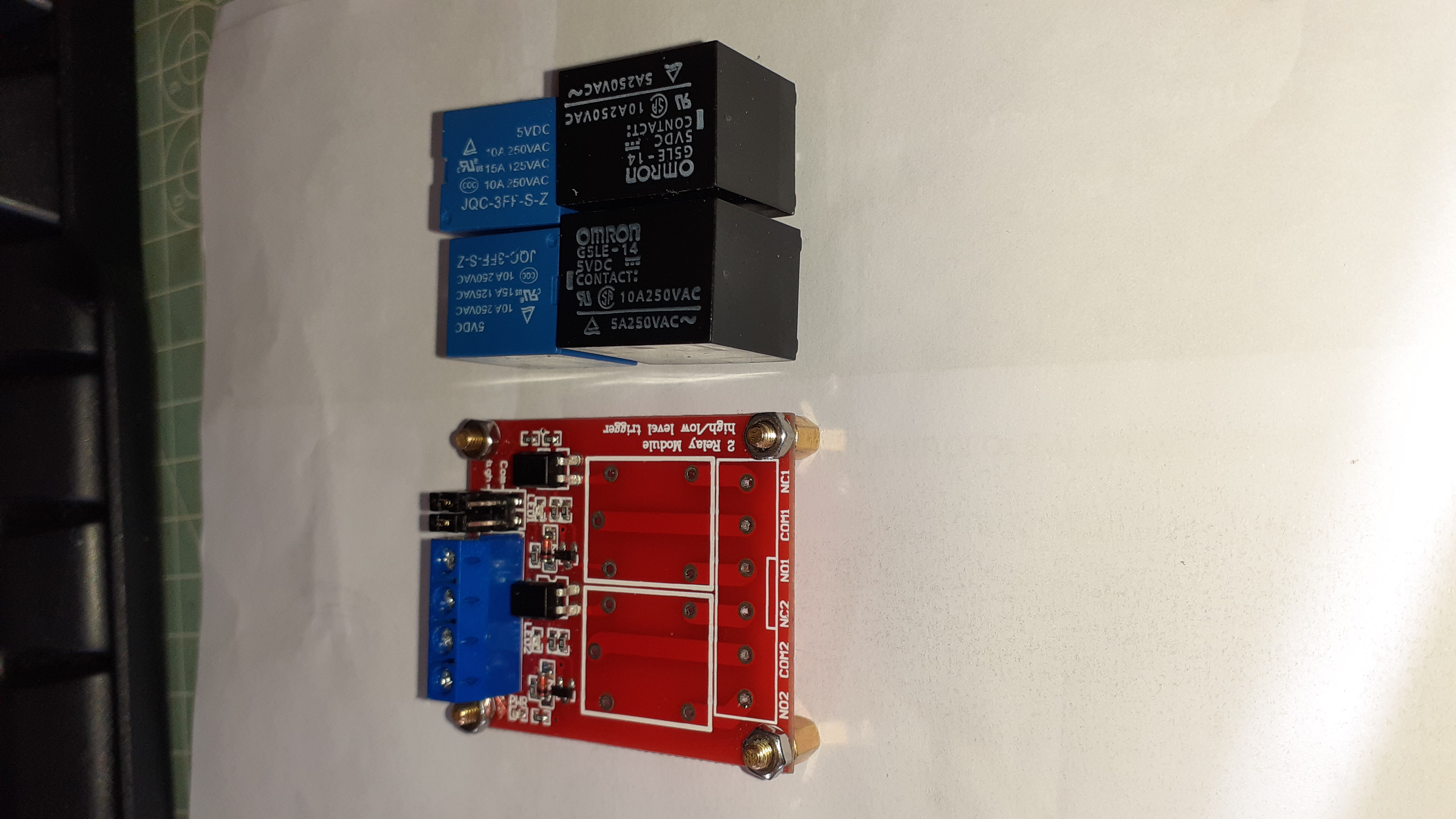
I found that Omron, a well established and respected maker of relays, have a product with a similar package size (only marginally larger) that can be fitted to the PCB without altering the board. The part number is G5LE-14-DC5. It is rated for 10A at 250VAC. The datasheet is here.
The Omron parts have the same pin footprint but the case dimensions were slightly larger. They fit onto the board but the screw terminal block had to be removed. Connection was effected using some header pins, shown in the final photo, which allowed the terminal block to be reconnected.
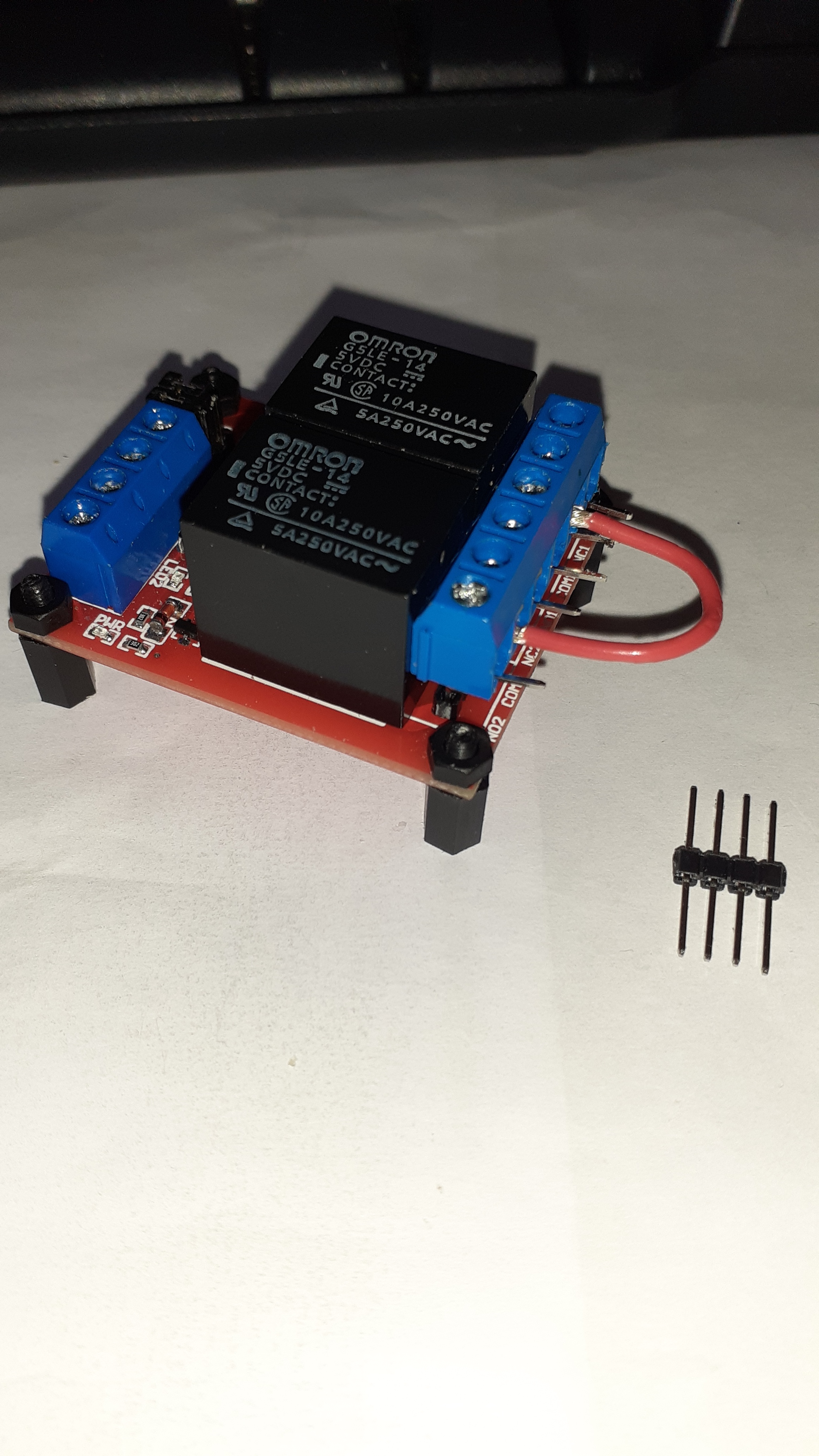
The moral of the story is that you get what you pay for !! Hopefully the will be no more welded contact issues
February 2023.
- Details
- Hits: 3674
Introduction
Recently I have been living away from my main station in noisy, low lying urban location which unlike my main station is a poor location for operating radio. The obvious solution to this was to run my main station remotely. This article describes how I achieved this using open source, freely available software packages and an Icom IC706 Mk2 G.
I was already familiar with the Raspberry Pi (RPi) series of computers and their headless operation with the remote desktop package RealVNC. This package is made available for free home use on the Raspberry Pi by the vendor and allows the remote operation of a RPi running what ever software you wish. It comes installed as part of all recent RPi software distros and the server only has to be enabled in the interfaces tab of the RPi configuration tool. To control the RPi all that is required is a client computer, typically a Windows PC, that is running the RealVNC client software, sometimes referred to as the viewer.
Transceiver control software
For the operation of the transceiver I chose to use FLRIG which is an open source cross-platform package. It is available as a precompiled binary on the RPi software repository but if you want the very latest version it is available from W1HKJ 's website and supports a very wide range of different transceivers, including my IC706 Mk2 G. Jason, KM4ACK gives an excellent tutorial on Youtube on how to do this. It has a nice simple GUI which allows mouse control of a transceiver.
Transceiver control interface
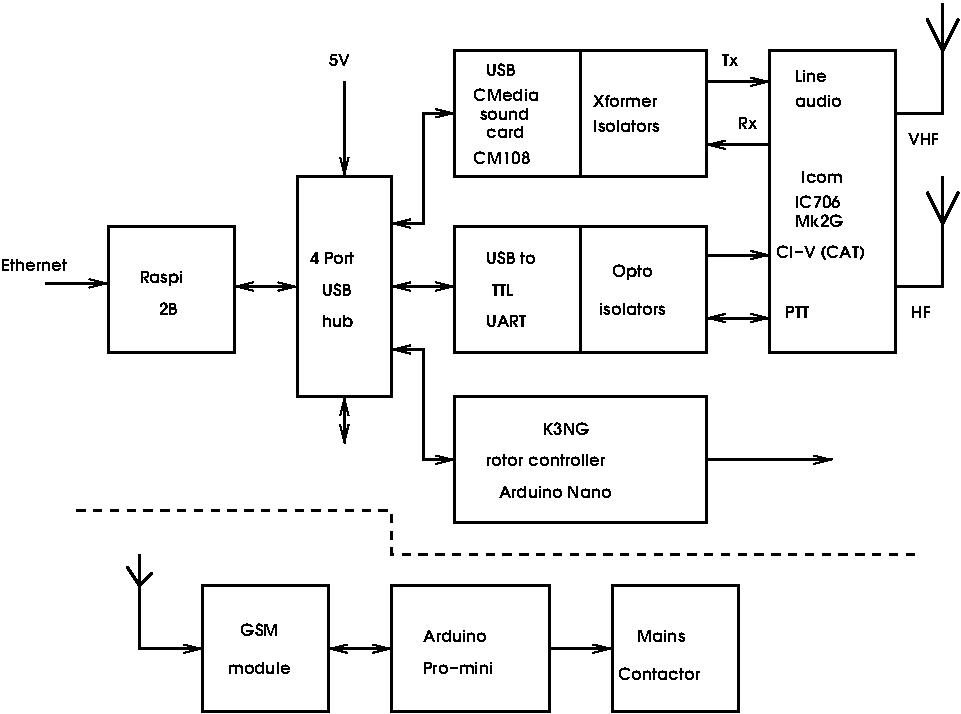
For the control interface I chose to build my own but it is perfectly possible to use a commercial unit such as the Signalink or Rigblaster types. A block diagram of my homebrew unit is below. I found it was important to incorporate 1:1 audio isolating transformenrs to avoid noise on the transmit audio.
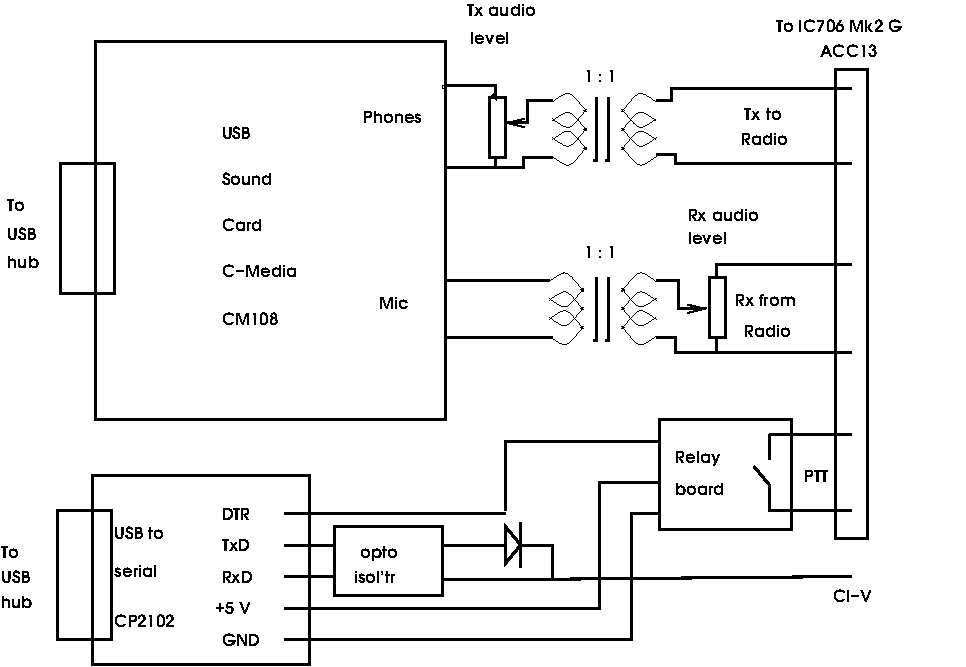
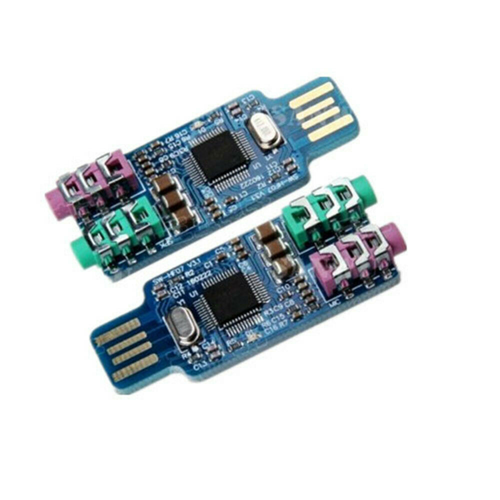
For the audio side I used a C-Media CM108 USB sound card. These are available on Ebay at low cost and work well in this application. the one I used is puctured below.
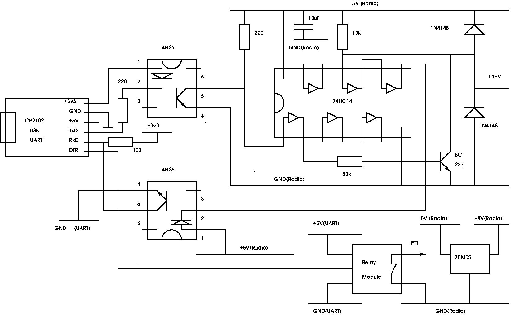
I also added opto-isolators to the CI-V interface to break hum loops and minimise the opportunities for RF inductive pick-up especially on the HF bands. Details of the isolated control interface are below. The circuitry on the right of the 4N26 opto-isolators is powered from the +8V pin on the IC706 13 pin ACC DIN socket.
I also built the whole of the control interface into a well shielded box with a good filtered IEC mains power connector.
As another general point I strongly recommend that you use a powered USB hub to connect the USB peripherals to the RPi. I have found that in general if you draw too much current from the USB ports on the RPi it can result in unreliable behaviour. For remote operation the last thing you want is a crashed RPi at the remote end requiring a power cycle to reset it.
The audio link
In order to use the radio it is necessary to pass the receive and transmit audio over the internet link. This in some respects was the toughest bit of the project to get working well and there are some observations later in this article about this process. For this task I used a package called MUMBLE. This is a package intended for computer gamers to discuss game strategy while playing games. It gives two way duplex audio transmission and can be made to work well in this application. It operates in a simal way to RealVNC in that the Mumble server (MURMER) runs on the RPi and the client on the remote computer. Again it is cross platform and can be downloaded from the RPi repositaries. There is a Windows MUMBLE clent which runs on the client PC. MUMBLE provides a number of digtal signal processing (DSP) functions but I found they do not play well with white noise and are best switched off or minimised in this appication. A useful and detailed tutorial on setting up MUMBLE for a remote station by Jason, KM4ACK is here on Youtube.
I found the audio link was the most difficult part of the project to set up and get working in a satisfactory way. I strongly recommend that when doing the initial set up you have access to both ends of the link so that you can measure the audio levels at the different stages, This was caused in part by the fact that the line audio levels on most amateur transcievers are not well defined or specified and best measured initially by feeding an audio signal generator into the line input to determing how it behaves. once you know how much signal is required to operate the transmitter properly you are then 90% of the way there!
Remote antenna rotation
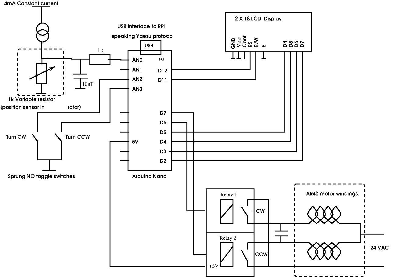
Once the basic radio remote functionality was established attention turned to pointing the 2m horiziontaly polarised Yagi remotely. The rotor in use is a venerable CDE AR40 which is turned either clockwise or anticlockwise by 24 volt capacitor start AC motor. The position is sensed by a 1 kOhm wirewound variable resistor. To control the antenna position a hardware interface to the RPi and suitable software were required. A search of the internet revealed the excellent K3NG Rotator Controller package on Github.This is a very versatile package that allows the position control of antennas by means of an Arduino microcontroller. To control the AR40 only azimuth control is needed and an Arduino Nano was quite adequate for the task. The package is setup by means of a configuration file for the particulat requirements of the rotor and the interfaces required. In this case the arduino was programmed to emulate a Yaesu GS-232A rotor controller. This meant that by making the RPi send and receive GS-232A commands it could turn the antenna to a desired angle and read out the position from the 1k variable resistor in the rotor. Running a terminal emulator on the RPi allowed commands to be typed to rotate the rotor both clockwise and anticlockwise as well as reading its current position. Later a GUI programme Pyrotor was found which presents a compass rose azimuth display on the RPi. desktop. Pyrotor was written in Python by David Fanin and is available here. It is a GUI for the rotctl/hamlib antenna rotor control program rotctl and is designed to work with the K3NG antenna rotor controller software.
The configuration file, rotator_features.h , for compiling the software that I used for my setup is here..
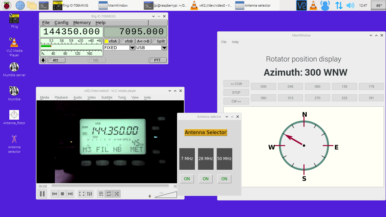
Remote station desktop
The dsktop on the RPi is shown below. All of the functions that can be controolled over the CI-V interface are available on the FLRIG window. The Pyrotor interface can also be seen. The CW and CCW rotation can be selected and manuallys halted when the desired direction is displayed. An image of the front panel of the radio has proved useful for debugging problems and monitoring the transmit output which is not available from the IC706 over its CI-V interface. A simple GUI also allows the selection of different antennas by means of a three way rotary coax switch.
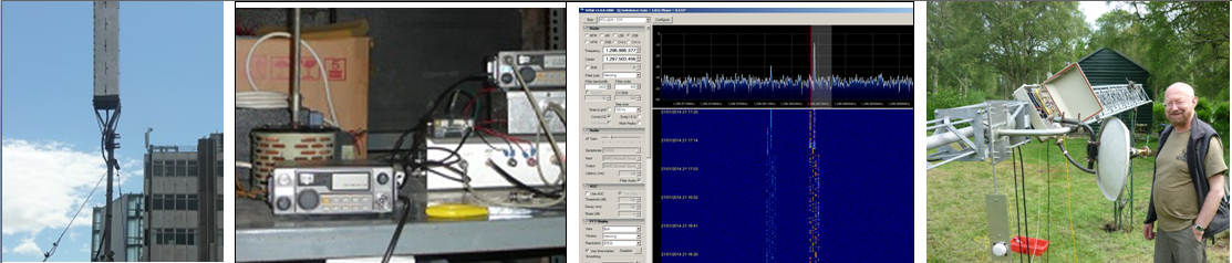
An overall block diagram of the controller is shown below alonw with a picture of my installation.
I also felt that it was wise to have overall control of the station via the phone system and added a phone link so that the staion could be powered down remotely independent of internet access. This is described below.
Remote power switching.
It was considered that it was useful to be able turn power to the whole setup off and on remotely. This provides a means of software crashes and means the station can be turned off when not in use. Small GSM cell phone modules are a available at very reasonable cost on Ebay. These are either based on the SIM800L Ublox module or the Neoway M590E module. I chose to use the Neoway module. These come as a small kit consisting of a PCB an M590E, a SIM card holder and a few SMD parts. The M590E module had clearly been recovered from some scrapped equipment but were found to work well. Combined with an Arduino and a SIM card these make a useful teleswitch. I used an O2 pay as you go SIM card in the setup. This cost 2 pence per text message and so a £10 top-up goes a long way!! Provided the SIM is used regularly the credit does not expire. The code I used is based on code on Github . My modified code is here. Pictures of the Teleswitch unit are below.
M590E Kit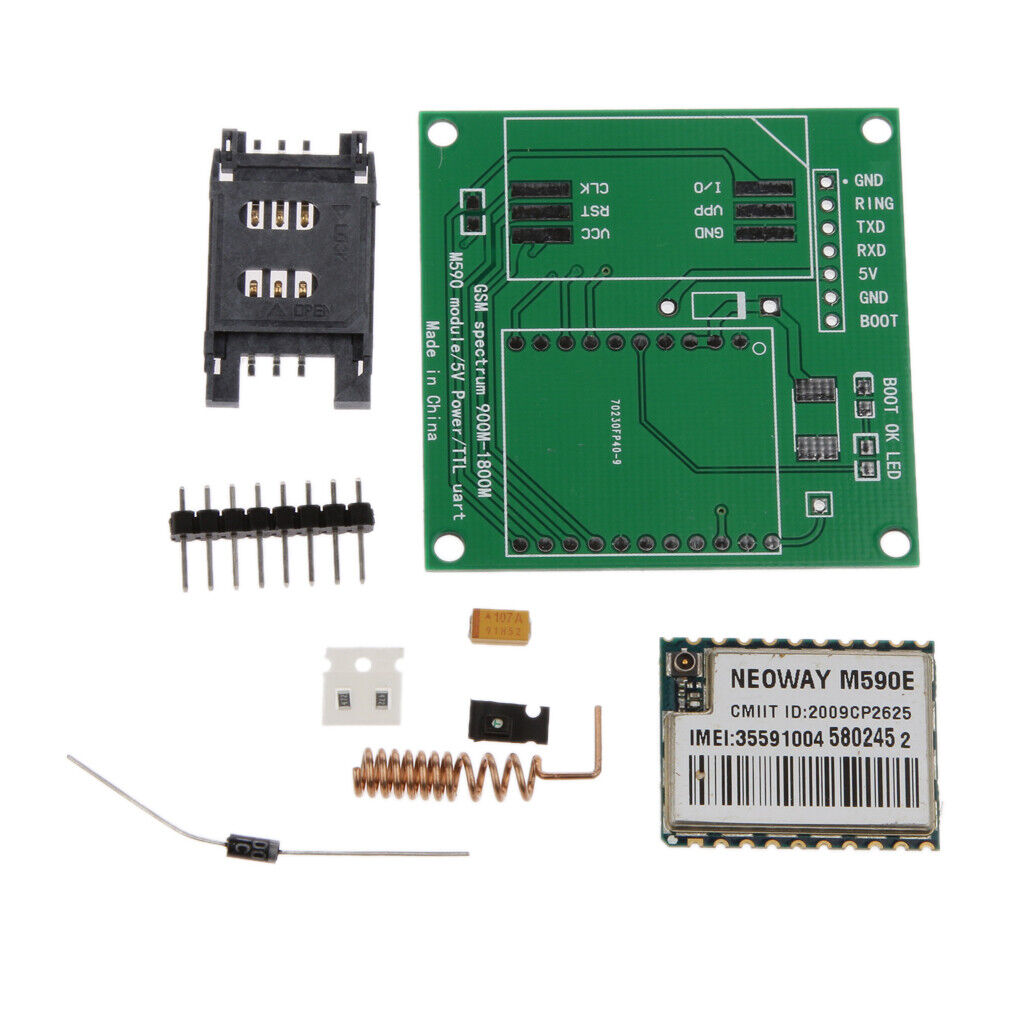
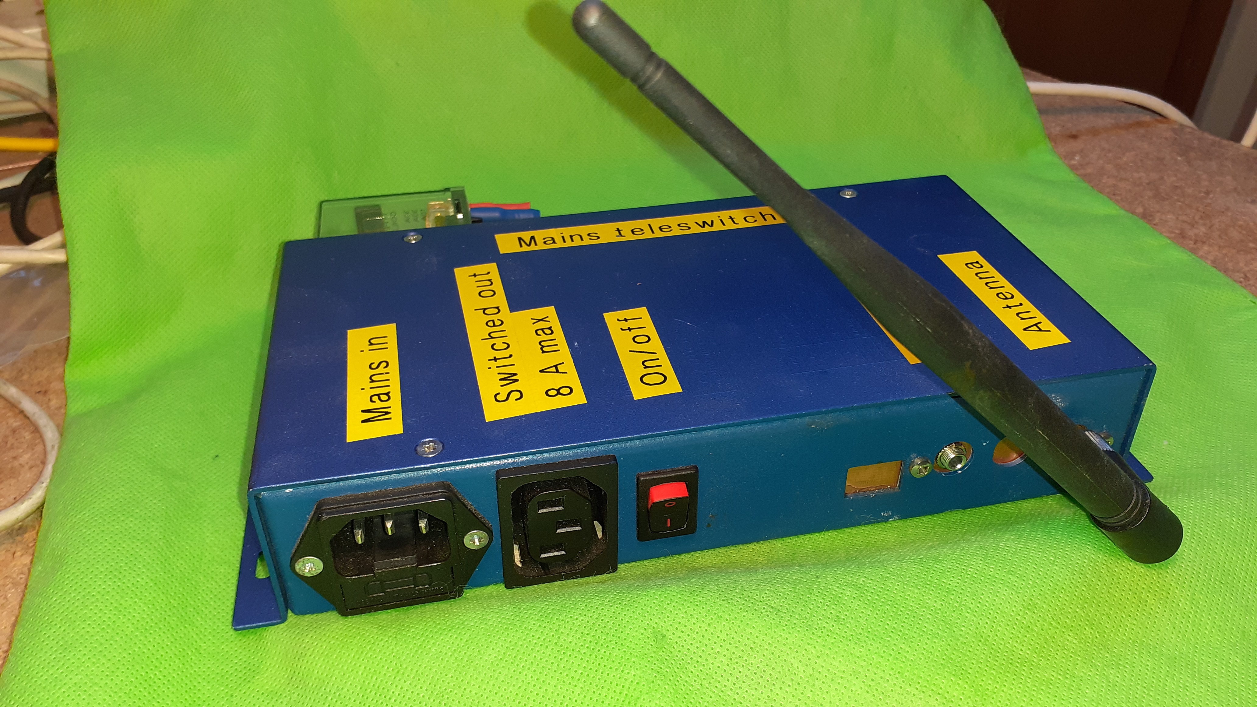
front panel
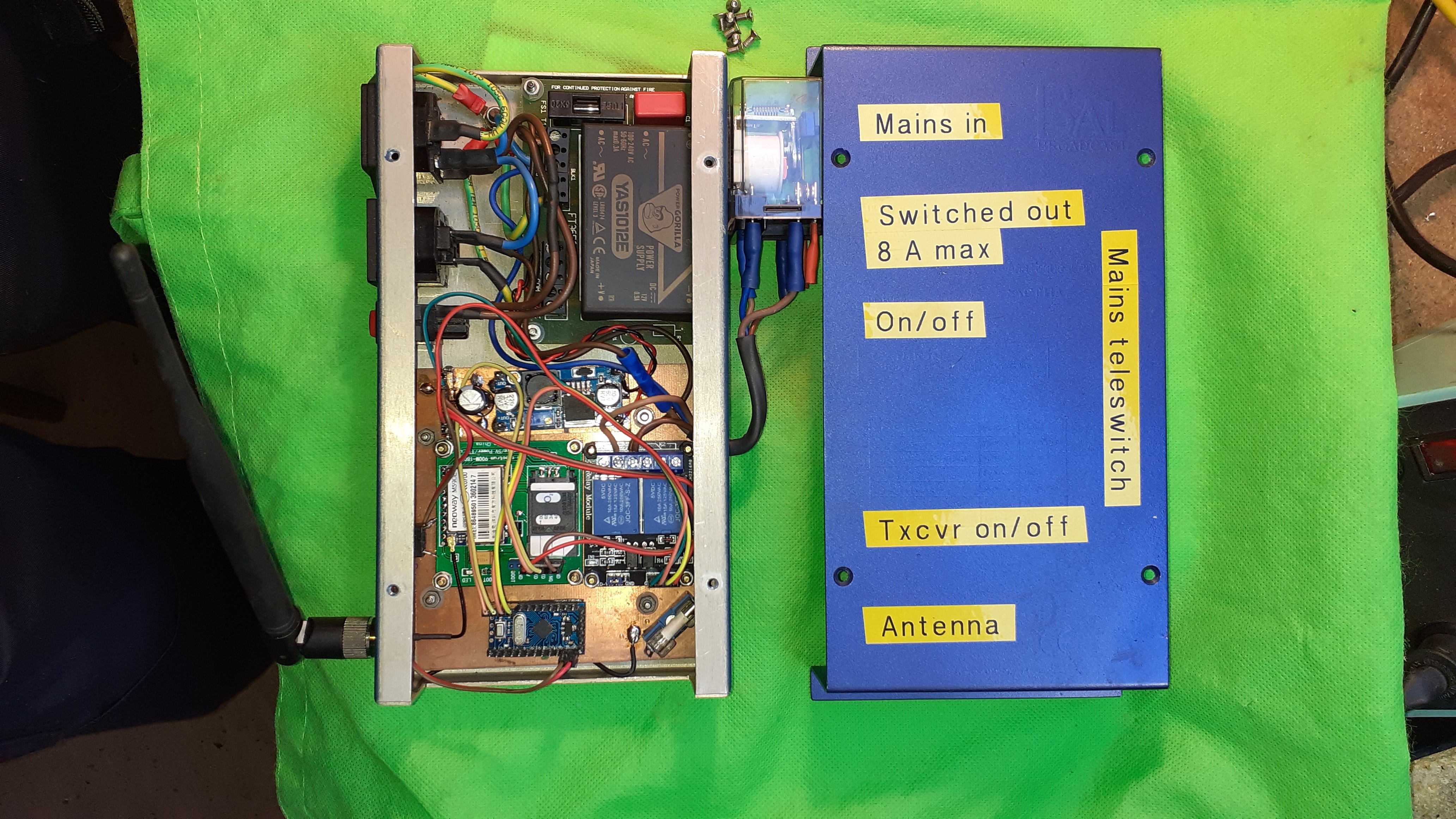
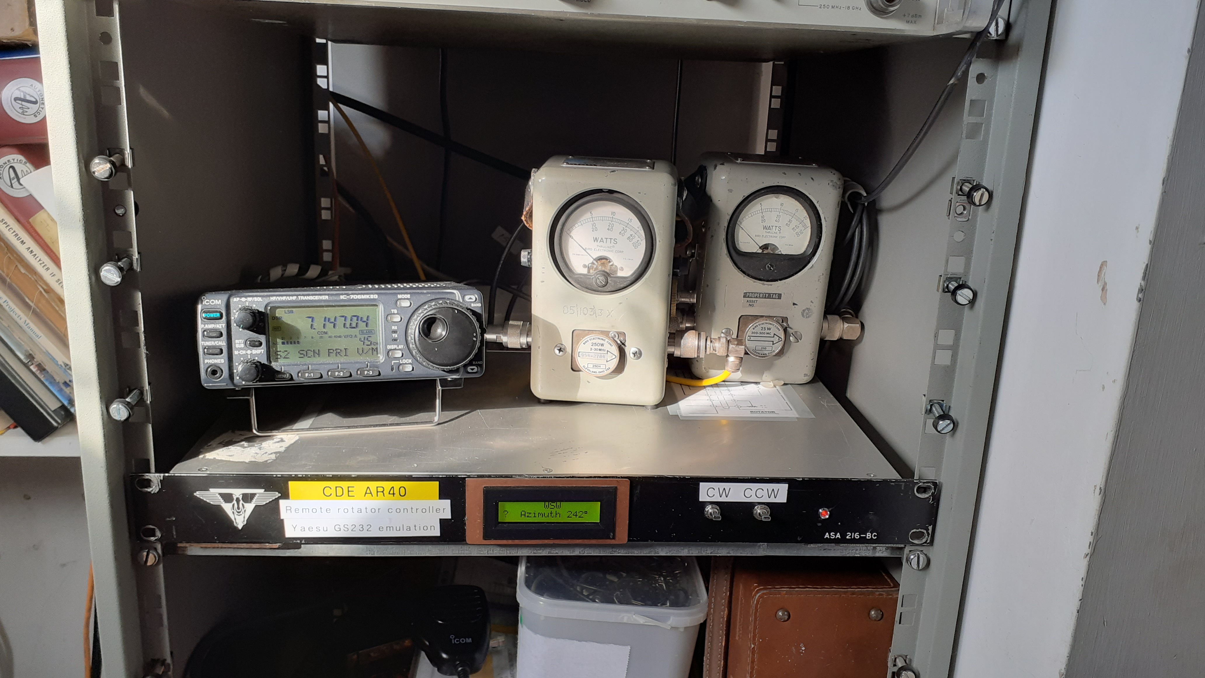
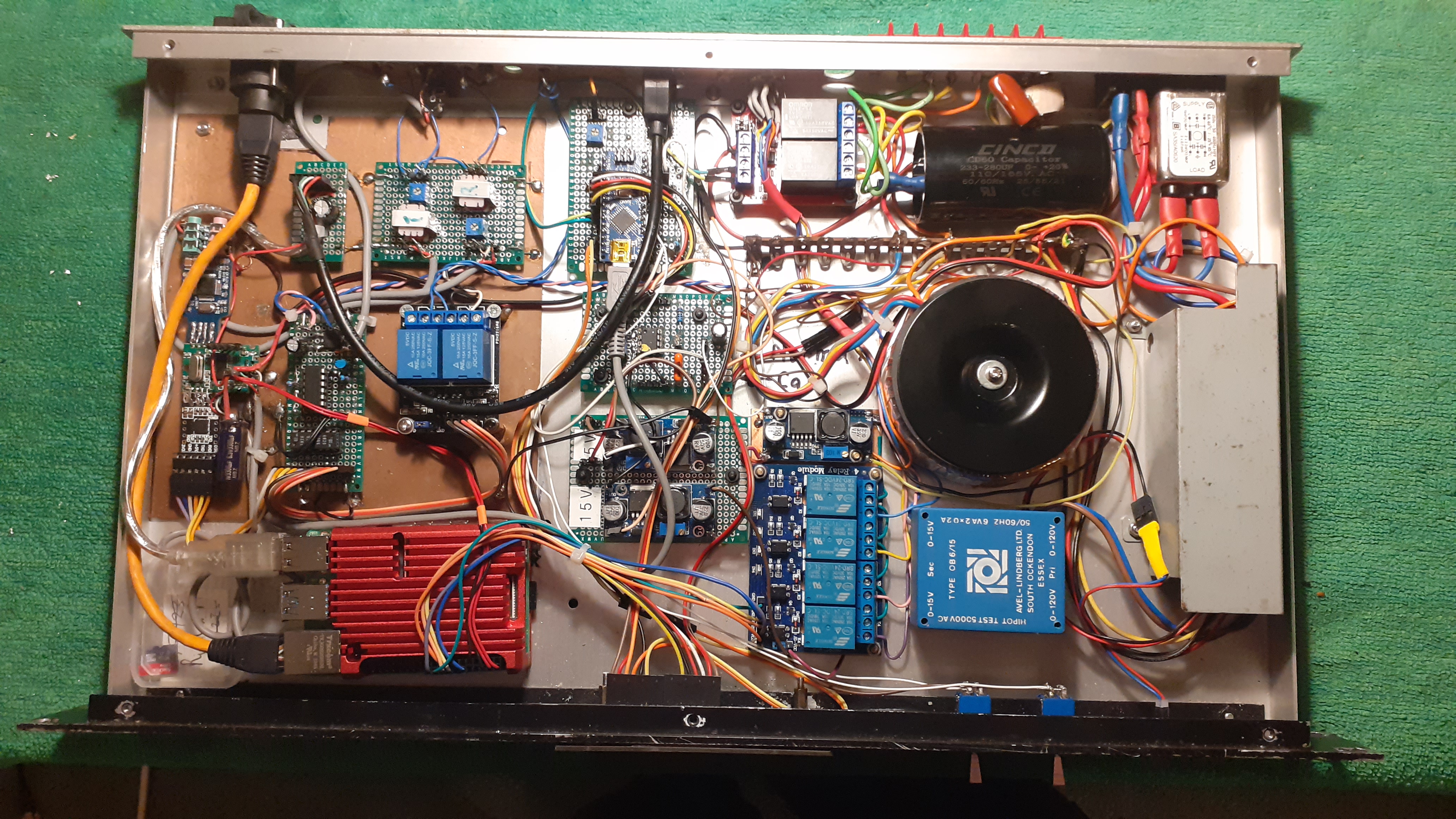
The overal installation.
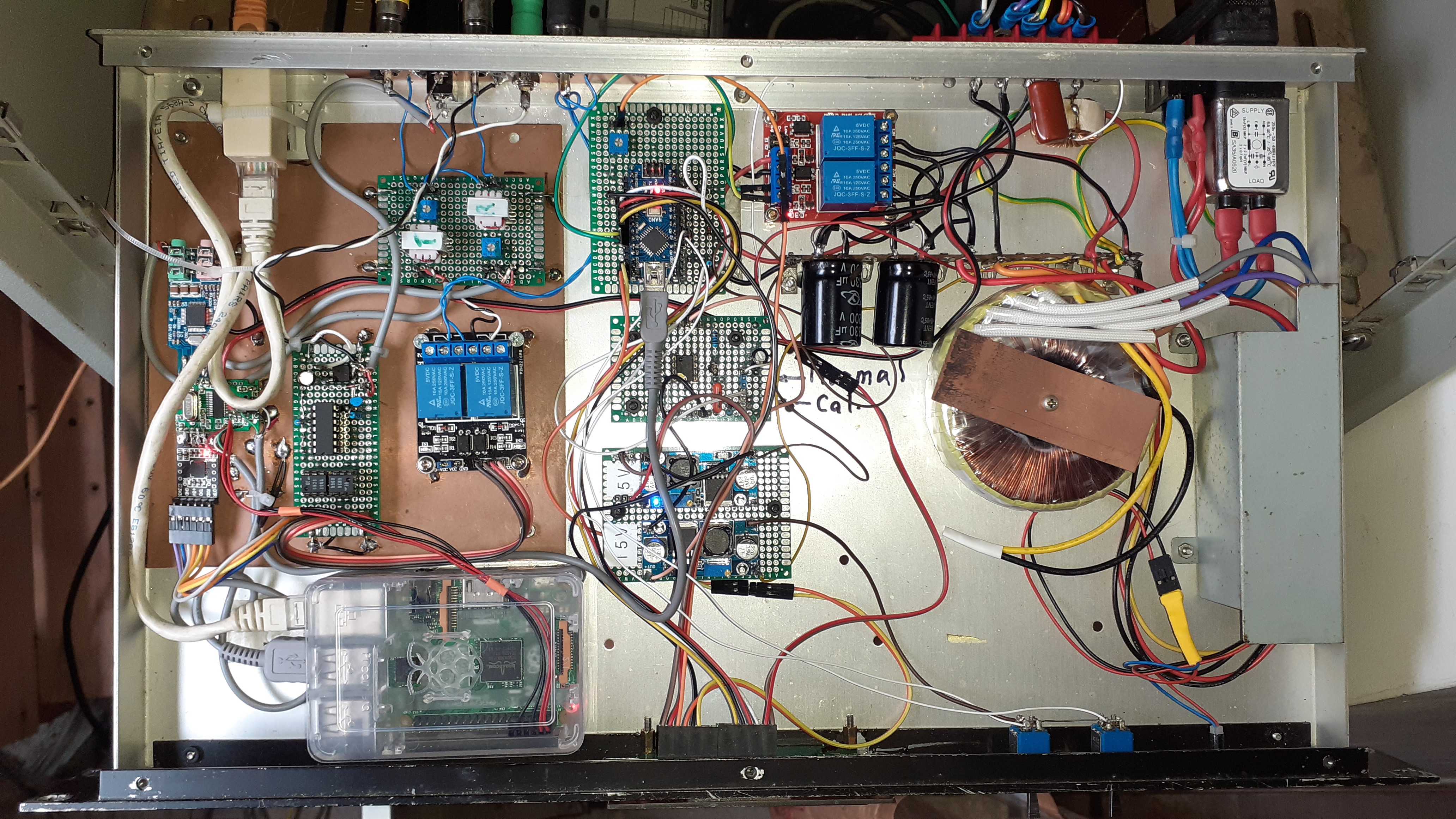
The entrails of the controller box in November 2022.
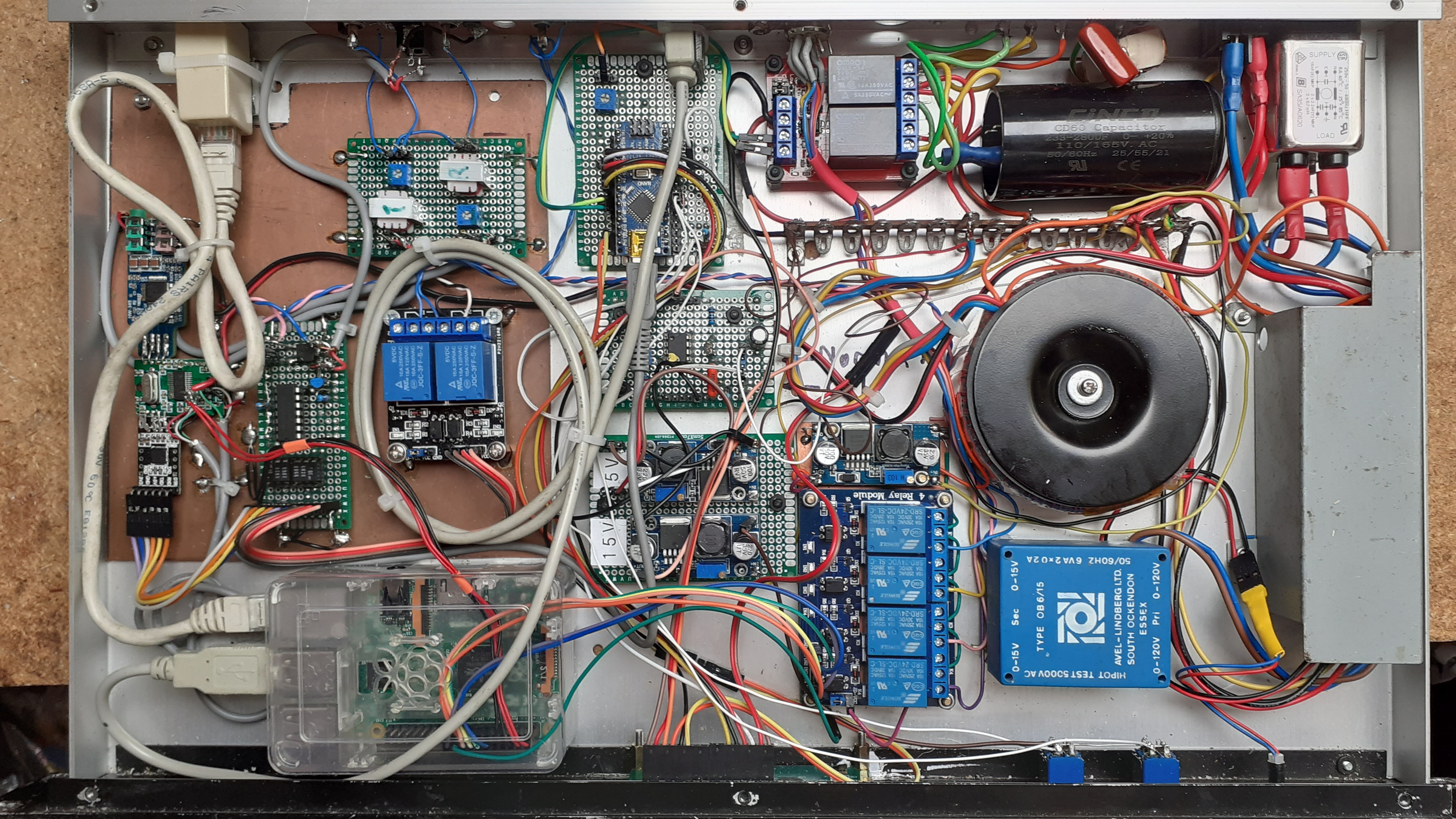
The Controller box in May 2023. Recent additions include four relays to cpulse a three way rotary coax switch for selection of different antennas. This is effected by means of GUI produced with a Python script running on the Raspberry Pi. An interface for a webcam has also been added to connecdt a webcam directed at the front of the IC706 to monitor the transmited output signal. This overcomes the inability of the '706 to give an indication of output power on its CI-V interface.
In 2022 gave a talk at our local radio club describing the development of my remote set-up. The slides are here.
Recently ( October 2023) I have been tidying up the wiring to some small extent and fitting some proper panel mount connectors to the back of the casing. This makes it easier to connect and disconnect the unit from the rack where it normally lives. These pictures are useful to me to keep a recond of the mods I have made to the unit as obviously I do not have normal access to the hardware! the latest picture for teh record is below.
Acknowledgements
- RealVNC for making remote desktop available.
- David Freese, W1HKJ for Flrig.
- Anthony Good, K3NG for Arduino Rotator Controller
- David Fanin, KK6DF for Pyrotor
- Jason A Oleham, KM4ACK, Various useful Youtube videos on setting up Mumble for radio applications. -Link
- Details
- Hits: 2870
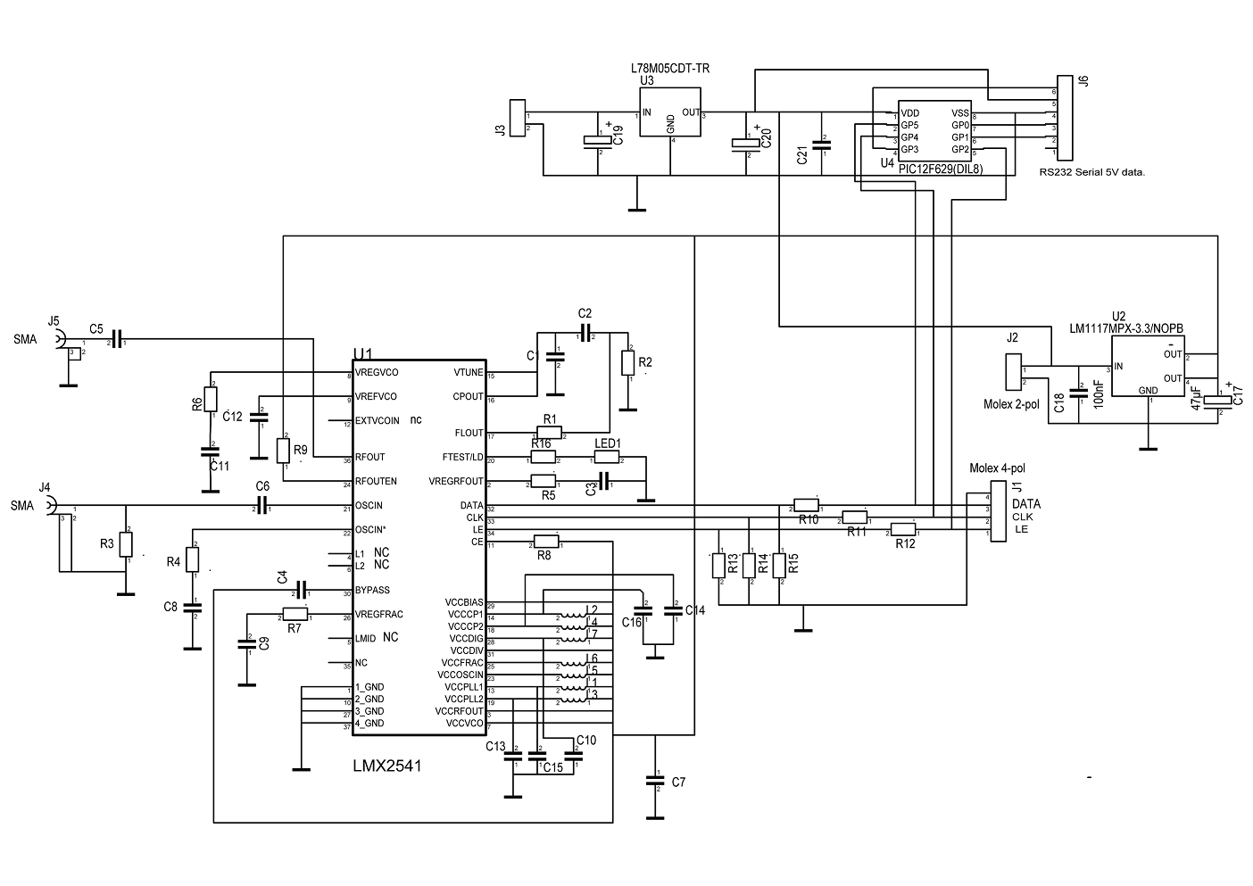
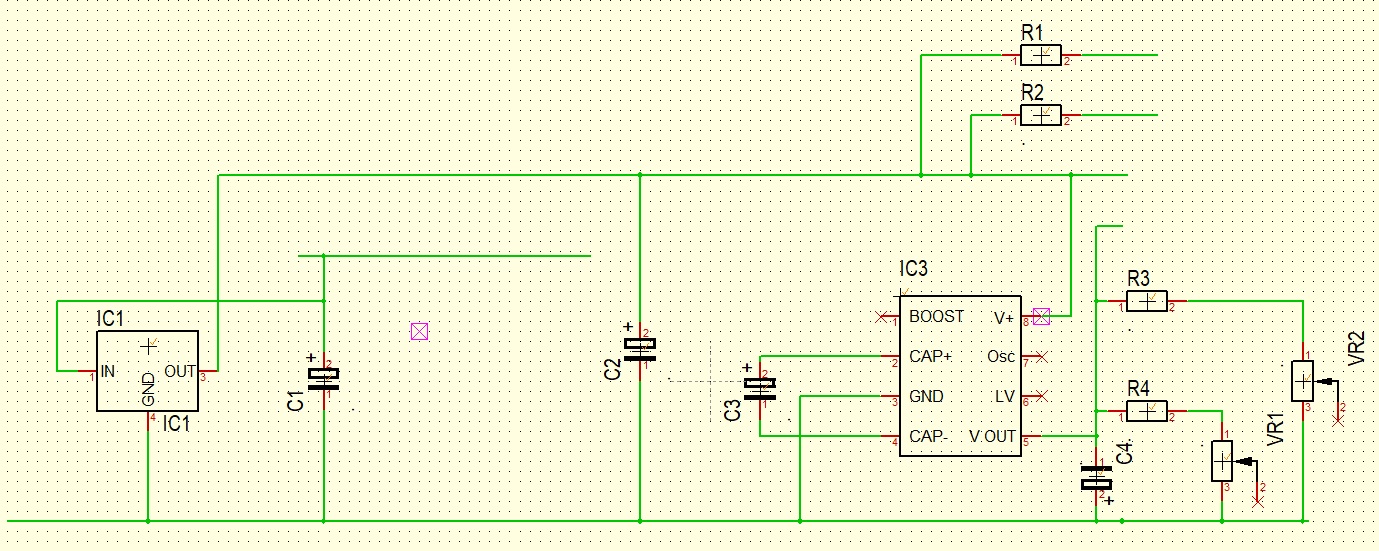
Schematic diagram.
; Bill of Material=C:\Users\Brian\Desktop\LMX2541Support(1)\PCB_design\lmx2541.T3001
; Date=10.May.2021 17:37
; Variant=AllVars
; PCB=<all component>
; Author=
;
Pos Name Value Package
1 C1 loop 0805
2 C2 loop 0805
3 C3 1uF 0805
4 C4 100nF 0805
5 C5 1nF 0805
6 C6 1nF 0805
7 C7 100nF 0805
8 C8 1nF 0805
9 C9 1uF 0805
10 C10 100nF 0805
11 C11 4u7 0805
12 C12 100nF 0805
13 C13 100nF 0805
14 C14 100nF 0805
15 C15 100nF 0805
16 C16 100nF 0805
17 C17 47µF 2412_ELKO
18 C18 1nF 0805
19 C19 47µF 2412_ELKO
20 C20 47µF 2412_ELKO
21 C21 100nF 0805
22 J1 4 way Pin Header
23 J2 2 way Pin Header
24 J3 2 way Pin Header
25 J4 SMA SMA_EDGE_CONNECTOR(#2)
26 J5 SMA SMA_EDGE_CONNECTOR(#2)
27 J6 6 way Pin Header
28 L1 1uH 0805
29 L2 1 uH 0805
30 L3 1 uH 0805
31 L4 1 uH 0805
32 L5 1 uH 0805
33 L6 1 uH 0805
34 L7 1 uH 0805
35 LED1 RED 0805
36 R1 loop 0805
37 R2 loop 0805
38 R3 50 Ohm 0805
39 R4 50 Ohm 0805
40 R5 4.7 O 0805
41 R6 4.7 O 0805
42 R7 4.7 O 0805
43 R8 4k7 0805
44 R9 4k7 0805
45 R10 1k5 0805
46 R11 1k5 0805
47 R12 1k5 0805
48 R13 3k3 0805
49 R14 3k3 0805
50 R15 3k3 0805
51 R16 47O 0805
52 U1 LMX2541 TI_NATIONAL_SEMICONDUCTOR_LMX2541SQ3030E-NOPB_0(#7)
53 U2 LM1117MPX-3.3/NOPB SOT223
54 U3 L78M05CDT-TR DPAK
55 U4 PIC12F629(DIL8) DIL8
BoM
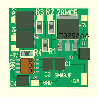
Parts placement.
3-D CAD view
CAD image
Tiled array of six boards (Top)
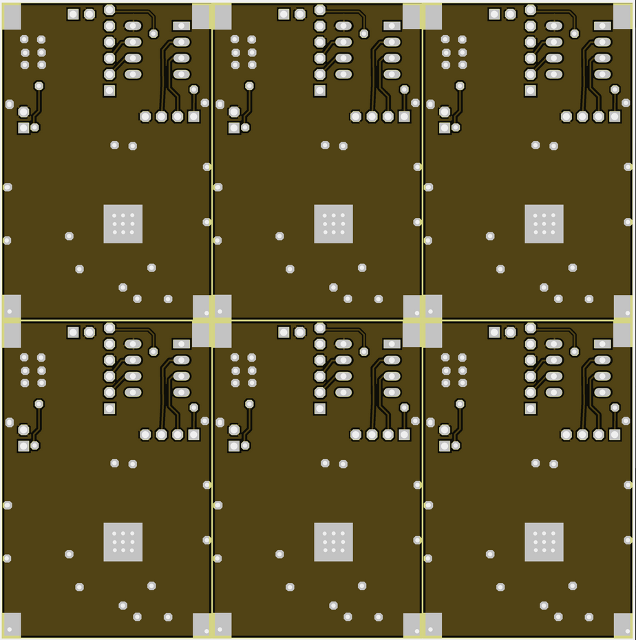
Tiled array of six boards (Bottom)
- You are here:
-
Home

- Uncategorised