There are a number of different PLL synthesiser chips available from different vendors that are useful in the design of beacon transmitters. FSK modulation is conveniently generated by continuously re-programming the frequency registers with data from a micro-controller. There are downsides to this apparent simplicity. Firstly phase noise (PN) and secondly key-clicks can be at unacceptably high levels.
PN can be minimised by careful decoupling and filtering of power supplies [1] and choice of suitably high reference frequency. A more tricky issue can be the key-clicks arising from the FSK keying process. These arise from various auto-calibration and initialisation processes that are triggered within the chips when the frequency is changed by register updates. The data sheets give few details of these as they are probably proprietary. An exception to this the ADF5355/6 and ADF4355/6 series for chips from Analog Devices which allow a designer some control of the over the auto-cal process which is largely responsible for the key-clicks.
In the AD5355 [2] the auto-calibration is controlled by bit 21 in Register 0. When bit 21 is set to 1 the auto-calibration is on and when 0 it is off. As auto-calibration is required for the correct operation of the chip it needs to be activated periodically. Also Reg 0 is used to do frequency updates by latching loaded data in from registers 1 and 2, so it must be loaded for every frequency shift. A solution to this is that, at the start of every keying cycle, a full initialisation is performed by loading every register as described in the datasheet and then frequency updates are performed by only loading Registers 2, 1 and 0 and twiddling bit 21 of Reg 0 to 0 during the keying cycle. If periodic full initialisations are not done loss of lock will eventually occur due to either temperature drift or transient disturbances. On page 22 of Rev.D of the datasheet it is stated that is is possible to "Disable the automatic calibration only for fixed frequency applications, phase adjust applications, or very small (<10 kHz) frequency jumps". As the present application involves small frequency excursions for FSK keying this is feasible.
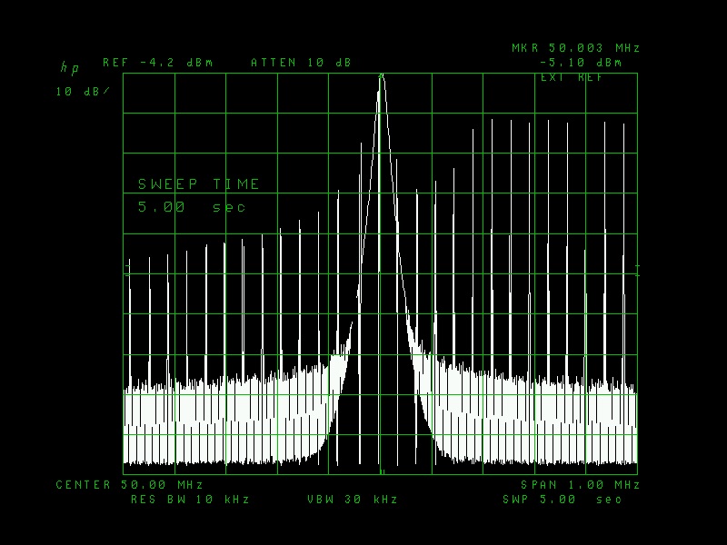
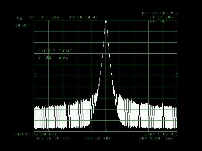
This keying scheme has been implemented in the code for the GB3RMK 50 MHz synchronous beacon near Inverness, which uses Bo, OZ2M’s PI4ino code [3], modified to do the timed frequency hopping running on an Arduino pro-mini. Figure 1 shows the effect of key-clicks and figure 2 shows the same plot with the Register 0, 1 and 2 being loaded with bit 21 of register 0 set to 0. The same keying scheme has been found effective at 10 GHz.
The modified ADF5355.cpp file for the PI4ino code is available on Github [4].
Finally before anybody else comments the ADF5355 does operate below 54 MHz, I was prepared to add a divide by two stage on its output for 50 MHz operation but did not find in necessary. Maybe I was lucky!

Figure 1 keying cycle showing the effect of key-clicks

Figure 2 Keying cycle with only registers 2,1 and 0 loaded with bit 21 of register 0 set to 0.
References
- https://gm8bjf.joomla.com/past-talks/15-reducing-phase-noise-pn-on-chinese-adf5355-boards
- https://www.analog.com/media/en/technical-documentation/data-sheets/ADF5355.pdf
- Bo, OZ2M PI4ino
- https://github.com/gm8bjf/ADF5355.cpp/blob/main/ADF5355.cpp

