Recently I was making some phase noise (PN) measurements using John Miles PN programme in his GPIB Toolkit using my 8566B spectrum analyser (SA) and was finding that there were spurrs occuring at 50/100 Hz intervals at the low frequency ends of the plots. A closer examination of the spectrum showed a series of close in spurs at 50 HZ intervals. (The line frequency in Europe). The spurs were at around 45 to 50 dB below the carrier which seemed to be too high. They are not normally obvious but at a 1kHz span and a 10 Hz bandwidth became quite apparent.
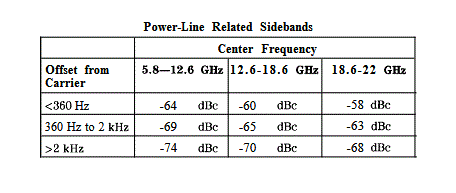
The HP8566B Installation and Verification Manual (HP Part No. 08566-90169) gave a detailed table of the sideband spur specification which showed conclusively something was wrong. The spurs were around 15 to 20 dB to high. This table is below.
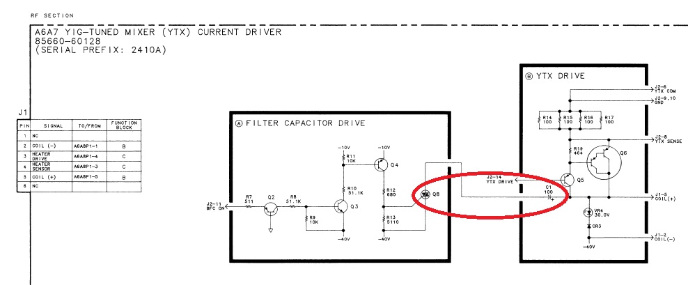
I was confident that the 12575.5 MHz Herley PLL I was using as a signal source was clean and was not the source of the spurs, so they were from the SA itself. I opened it up and checked the power rails for ripple and they were all perfectlty clean and set to the correct voltages. At this point I was assuming that the sidebands were being caused by some spurious modulation of the first YTO (first YIG local oscillator) in the analyser. I checked out the capacitors in the YTO driver circuitry and all seemed fine for both ESR and capacitance. On consulting the HP 8566B Service and Repair manual pages on the A6A7 module I discovered that the YTX (YIG tuned mixer) was a known source of power line spurii. The manual suggested that noise on the tuning current fed to the coil of the YTO modulated the incoming signal which became visible on the display as spurs at resolution bandwidths of 100Hz or less. The solution adopted was to switch a 100uF (A6A7C1) electrolytic capacitor across the the coil to bypass the residual ripple noise as shown below. C1 is switched into circuit across the YTX coil by the 2N6073 triac, Q8.
As a crusty old EE it struck me that this was not a good way to treat an electrolytic capacitor and expect it to have a long life. I was aware of the history of this particular 8566B (serial number 2332A02879) and I knew that I was its first custodian after HP/Agilent and that it was unlikely to have been used on narrow bandwidths very much. It had probably come from a HPIB automated production line environment. It was highly likely that the capacitor had been seldom switched into circuit to keep its dielectric "formed"..
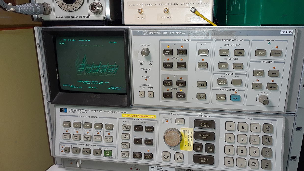
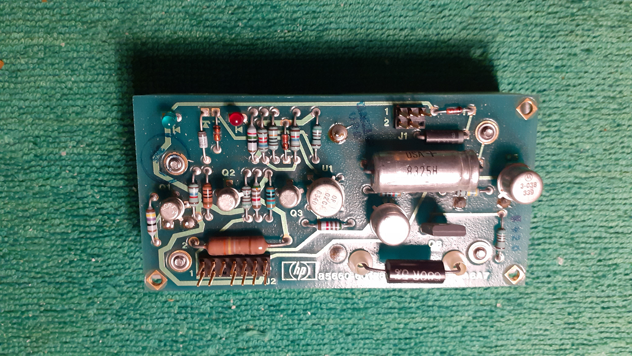
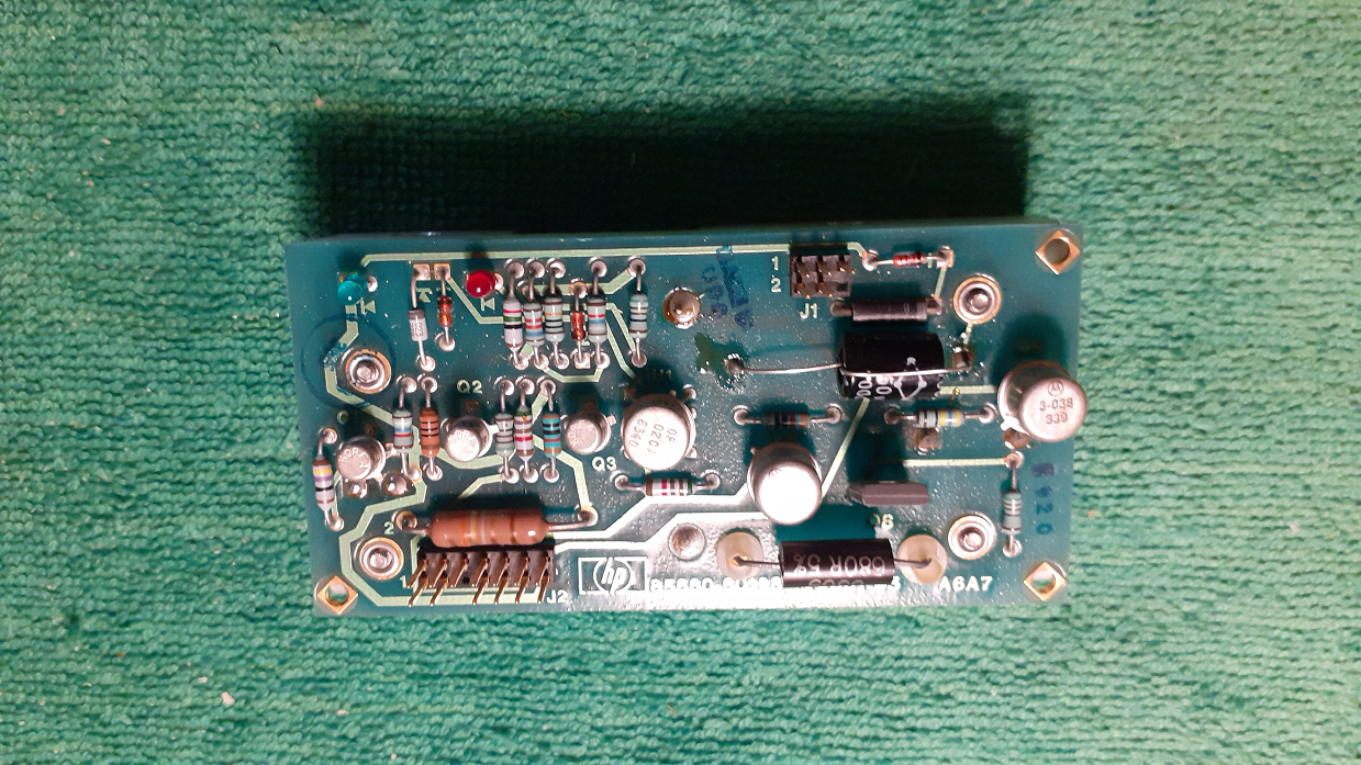
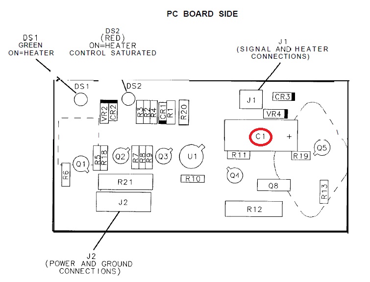
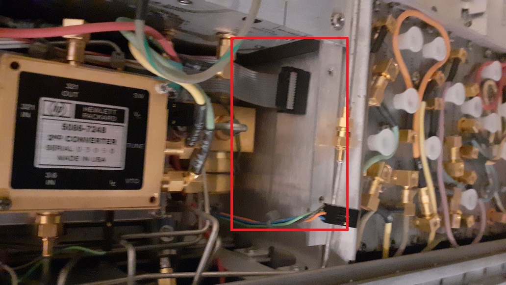
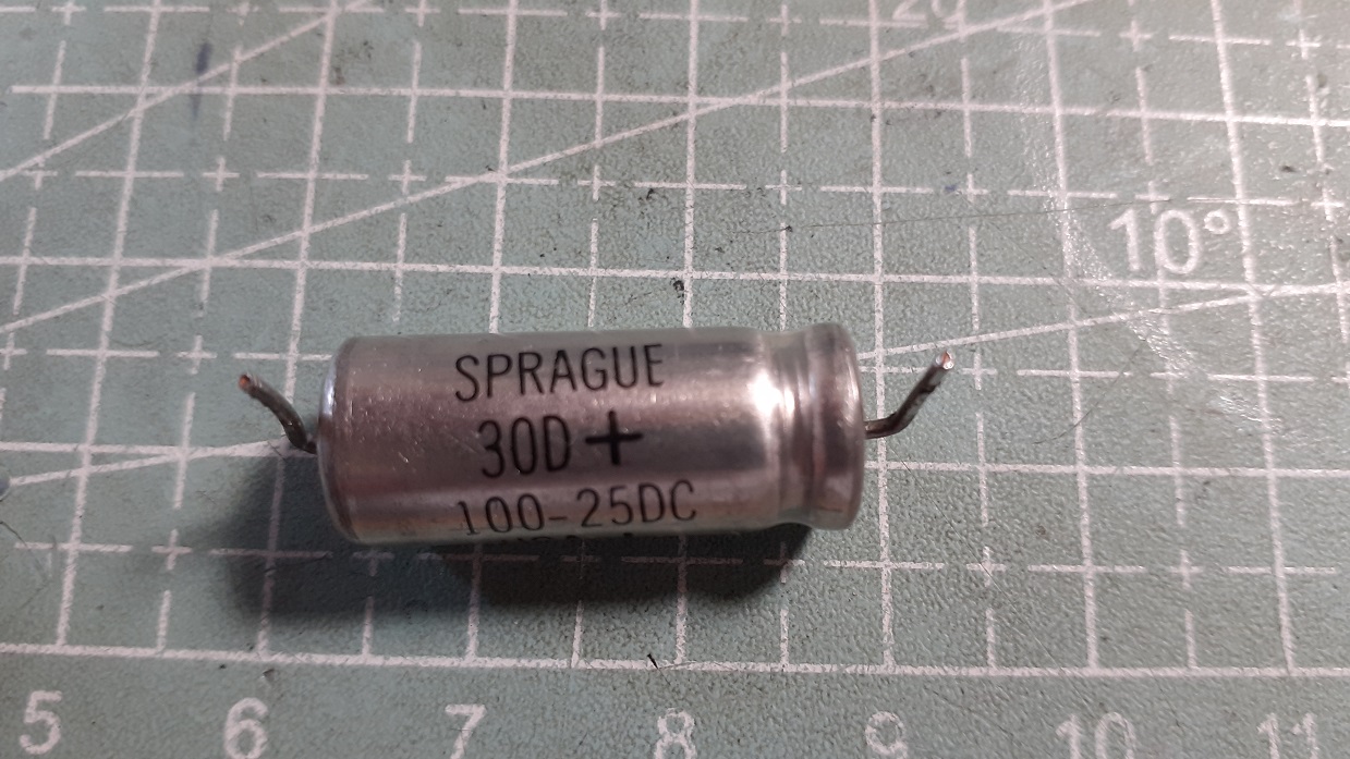
The coil bypass capacitor (A6A7C1) is on module A6A7 which is located at the right hand side of the rf/mixer area accessed below the bottom cover. The module is easily removed by undoing two countersunk screws and unplugging a PCB header connector and a ribbon cable. On checking C1 looked in excellent physical condition but on checking with an ESR meter was open circuit. The pictures below show the original capacitor and its replacement along with the board layout.
The location of the A6A7 board is here.
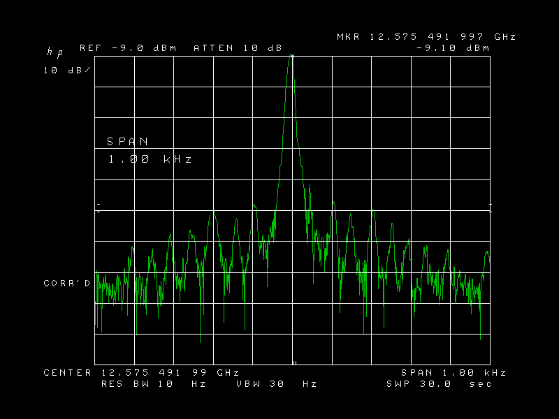
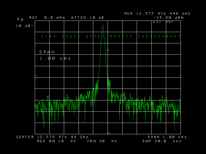
After replacing A6A7C1 the spectral plot looked like this with the spurs largely below the PN sidebands of the Herley PLL.
A close-up of the offending capacitor. It is in excellent physical shape but not there! Now perhaps I can remove that yellow "Out of band responses OOS (Out of Spec)" sticker on the front panel.
GM8BJF 28/09/2020