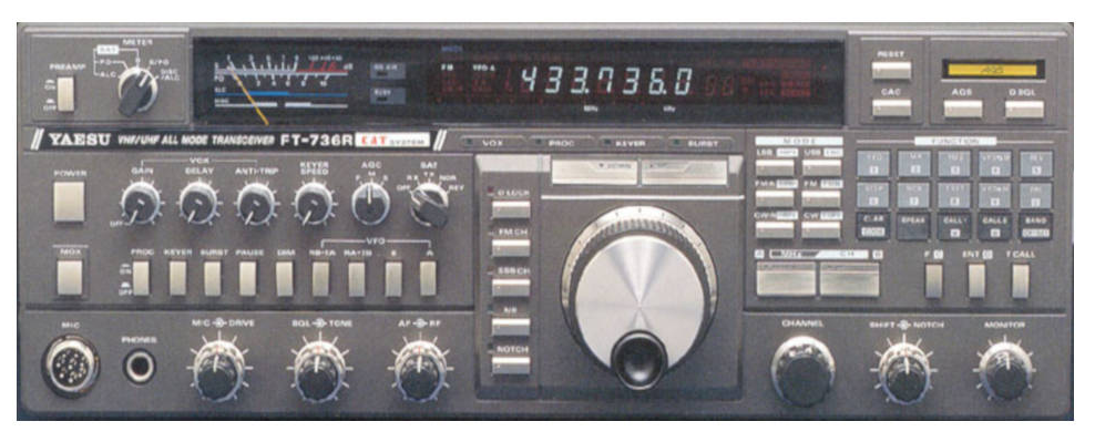
I have owned a FT736R for over 25 years and have been very happy with it. It has given me good service. It is fitted with the 6m and 23 cm modules. A widely recognised weakness with the radio is its switched mode power supply. It is an elderly design that is quite inefficient by present day standards and runs hot on account of four high wattage resistors which dissipate energy. One consequence of this is that several of the electrolytic capacitors “dry out” over time and lose their capacitance to a point that the power supply will not start up when switched on. Most other owners I know have re-capped their power supplies and I was no exception. Additionally, about a year ago my unit developed another fault whereby by the supply would make a ticking noise on transmission speech peaks. This was eventually traced down to a 10 mH inductor in the feedback circuitry which had gone open circuit. A replacement was sourced which seemed to cure the fault but I noticed that on transient loads and speech peaks the power supply kept tripping. I assume that it was probably due to the replacement inductor not having exactly the same characteristics as the original Yaesu part which looked to be a “special”. I decided it was time to think of replacing the whole PSU.
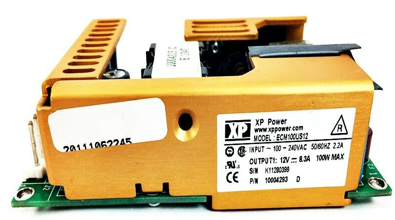
I remembered that I had seen an article some years ago about fitting a replacement by Harvey Laidman, W8DX in CQ Magazine but could no longer find a copy. (I subsequently found a copy). It was in the June 2006 issue on page 28. I found mention of the article on the FT736R IO Group and found that this was the part recommended . It seemed to be available in the US but was on a long lead time so I started to search about for a more available part. For EMI and safety reasons I wanted to use the original perforated steel enclosure to encase/screen the replacement PSU it had to fit in a footprint of 80 by 140 mm and be less than 40 mm high. I also wanted the replacement to have a good EMI specification. Most of the standard modular supplies have a width of 90 mm and would not fit the available space. I looked at the catalogues of the usual distributors and settled on a unit manufactured by XP Power, the ECM100US12. This has a footprint of 64 by 115 mm and height of 31 mm so would fit comfortably inside the original casing. It also runs from either 110 V or 230 V line voltage without switching. It is available for around £70 - £80 from a number of different UK/European component suppliers such as RS, Farnell and CPC and sometimes appears on EBay. The data sheet states it has industrial and medical approvals and it uses a two section mains input filter with two cascaded bifilar (common mode) chokes. It can supply up to 8 amps which is more that the radio requires on FM modes. Although it is nominally a 12v supply it can be adjusted up to 13.4 V which runs the radio quite adequately.
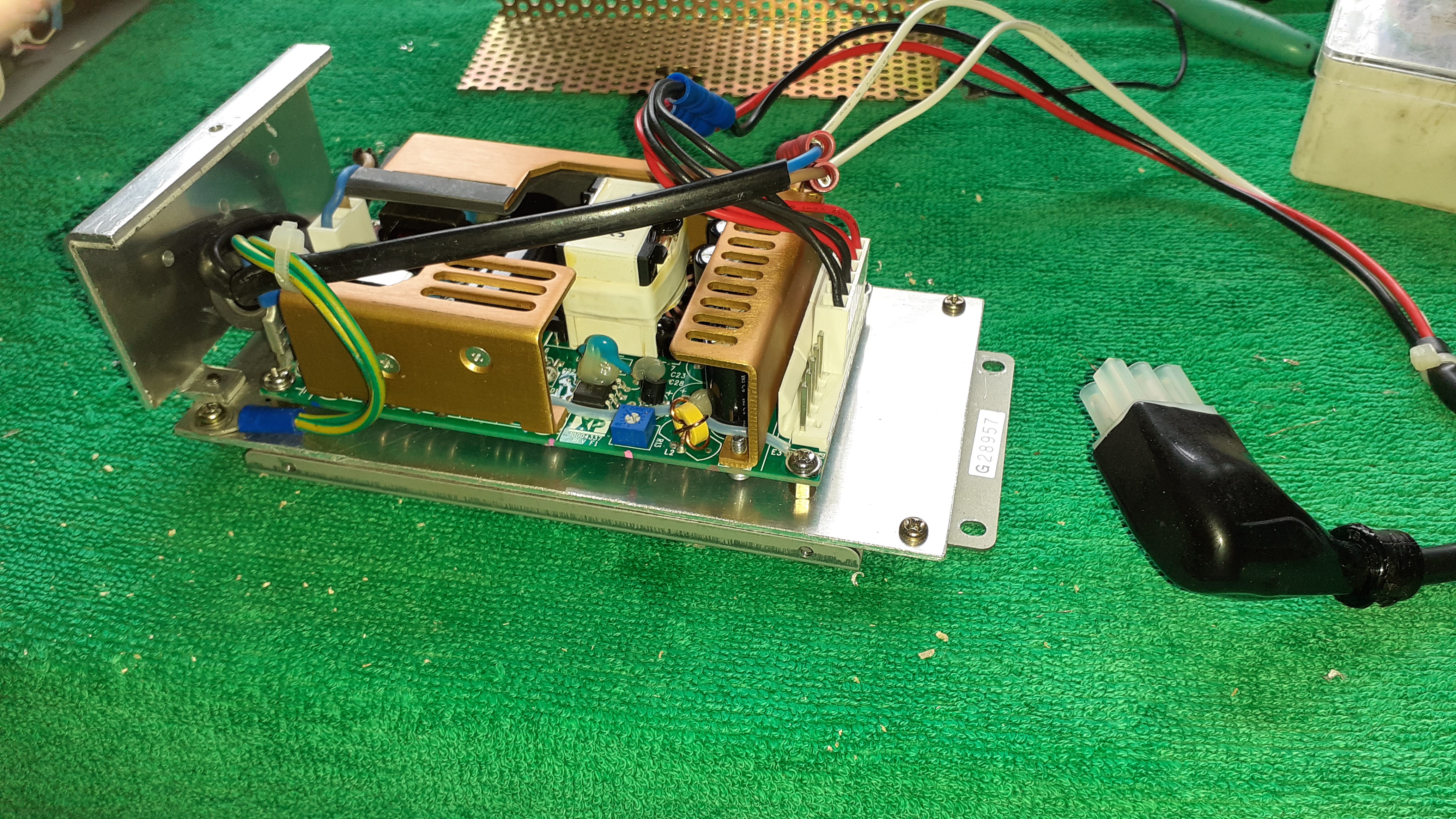
To fit a replacement first remove the original PSU from the radio. To do rhis remove the three screws on the heatsink back plate, and the two self tappers securing the PSU base at the front of the unit. Slide the PSU forward and raise it from the main chassis. The cable clamp/bush in the back panel can now be released to take the PSU free of the chassis complete with the 6-way JST connector. The PSU can now be dismantled by removing the screws securing the perforated cover and the PCB to the base plate. Recover all of the metalwork including the heavy gauge aluminium end plate. Carefully store all the screws as these will be required for re-assembly. Cut a piece of 18 SWG sheet aluminium to the same size as the original Yaesu PCB to act as a mounting plate for the new PSU and drill six fixing holes using the PCB as a template. (Two are for the aluminium end plate.) Also drill fixing holes for the new PSU and mount it on short pillars. Short leads with line input (3-way Molex) and DC output (12-way Molex) connectors were prepared. (Connector details are below).
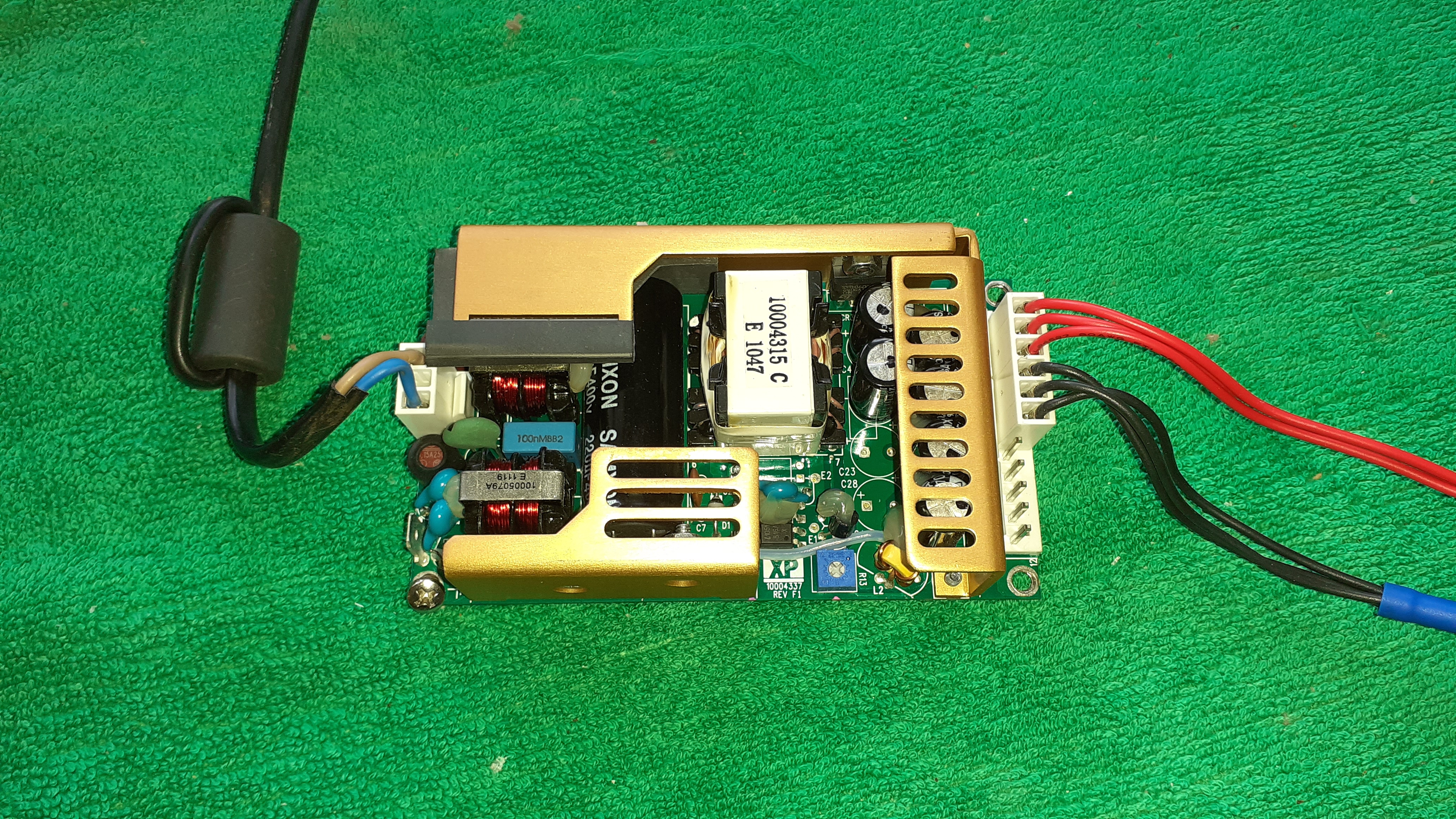
The power supply with connectors and short tails. The Molex connector shells and pins were as follows from RS. Links are to the RS catalogue. (A slight cock-up was made in ordering to 12-way output connector but a 6-way one sufficed!). Pins 9 -12 are unused.
|
SPOX 3.96mm female crimp housing, 3 way |
Molex 43061-0003 |
|
|
SPOX 3.96mm female crimp housing, 12 way |
Molex 09-50-1121 |
|
|
Crimp Term,18-24AWG,phosphor Bronze,reel |
Molex 39-00-0021 |
The short tails were connected to the original Yaesu cabling with crimp connectors.
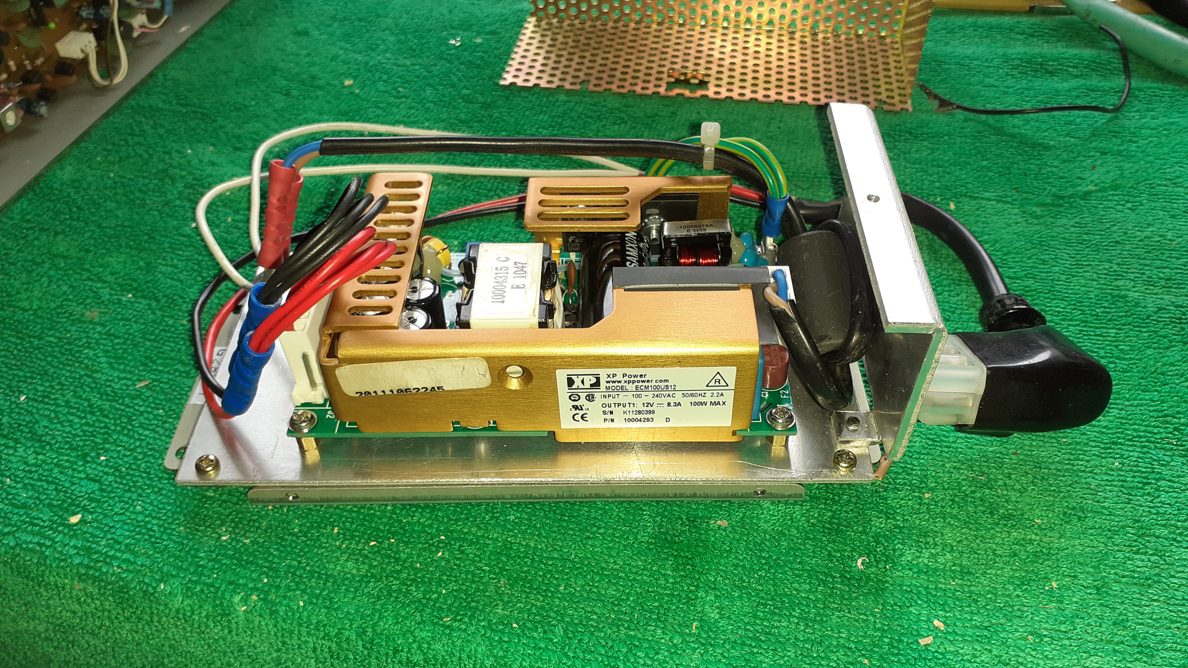
The PSU assembled into its original casing and back in the radio. The aluminium baseplate is visible where the PCB with the input and output connections and the voltage selector were.
While I was working on the radio and had it apart I decided to rewire the internal mains switch to improve safety. The Power switch on the front panel it is a 2-pole mains voltage rated part but one side is used to switch the 13.8 V DC line while the other side is used as the 230V mains switch. The problem is that the switch is in the neutral side of the power feed to the PSU. This is very bad practice as the live is permanently connected to the PSU. The Y-Capacitors in the PSU are subject to full mains voltage as long as the radio is connected to the mains. NOT GOOD!!! I decided that as I had only ever run it off a DC supply to test it I could dispense with the low voltage switching and use the double pole switch to properly isolate the radio from the mains when switched off.
I was able to do it by running new correctly colour coded line and neutral wires to the front panel switch and I was able to utilise the existing Yaesu (white) wires that were already in the harness as the returns to the fuse and backplate. I also had to rearrange the fuse wiring. I now have it arranged so the L and N come off the pcb on the back of the IEC socket directly to the switch. The fuse has been rewired so that it is in the L return from the switch before going to the 6-pin JST connector on the back. The L and N pins on the JST socket have been swapped as I was trying to preserve the original wiring as much as possible, but I see no harm in that. I have cut a piece of clear plastic so that it clips over the back of the mains socket to prevent the ingress of passing fingers as had happened! I also enclosed the front panel mains switch in heat shrink.
Overall the radio runs much cooler with its new more efficient power supply and will hopefully continue to give good service for some years.
31 May 2020.
Addendum
Notes on Mutek replacement front-end kits
Recently the has been some discussion on the kits that were available from Chris Bartram's, G(W)4DGU's, company Mutek back in the mid/late 1990s, These were to improve the sensitivity and the strong signal handling performance of these radios. There were two versions of the kit. The original kits consisted of four PCBs.
1. A 2m replacement front-end
2. A 70cm replacement front-end
3 A mixer and downconverter for the 70cm board (47.43 Mhz IF)
4 A board with a 13.690 MHz crystal "roofing" filter to improve adjacent channel rejection
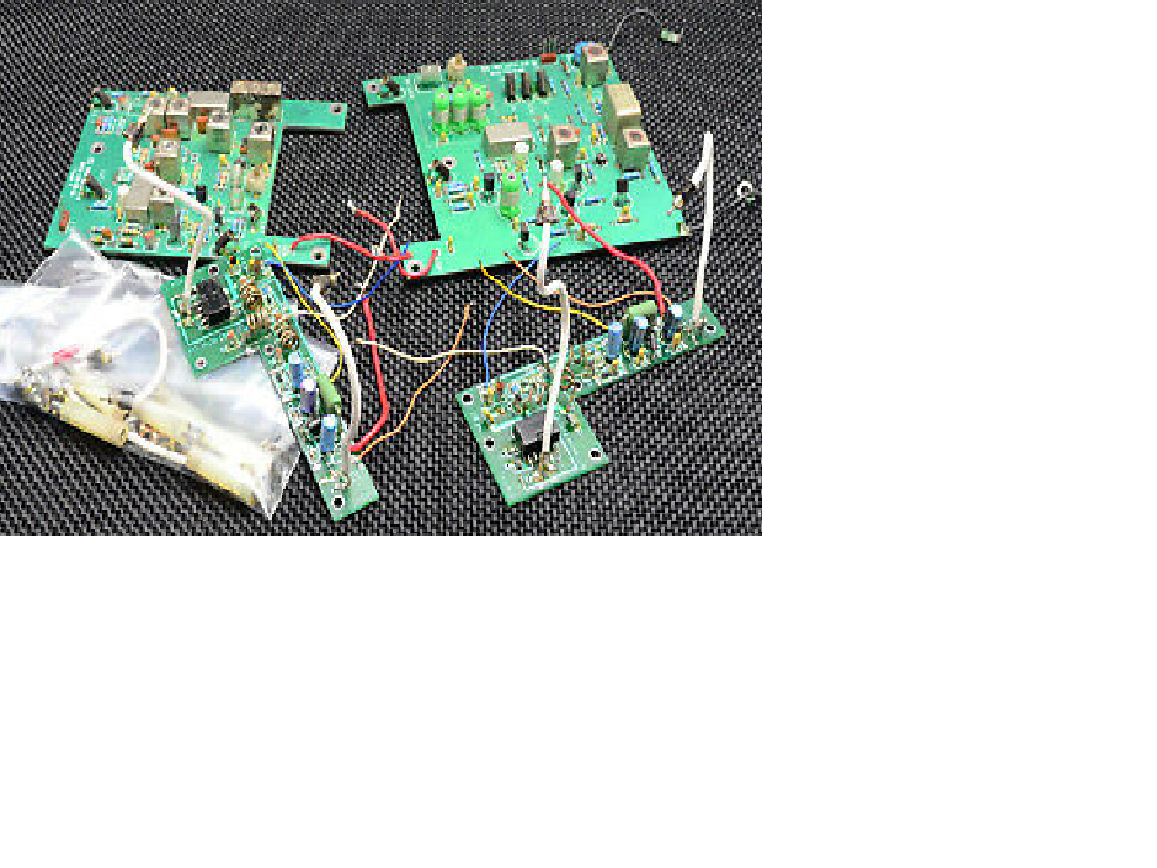
A somewhat messy picture of a four board kit on Ebay!
A set of fitting instructions for the four board kit is here.
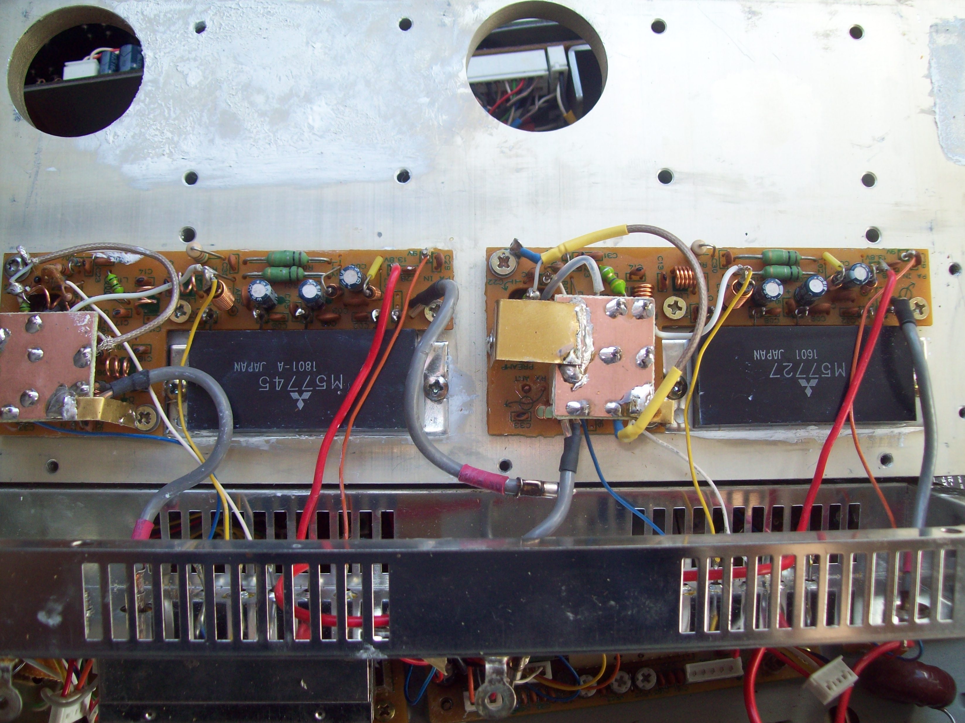
Later production kits consisted of the two front-end PCBs and a combined single IF board with the roofing filter. This combined board was housed in its own screened housing and fitted above the central 2m main unit PCB in the upper deck of the radio. I believe these kits were fairly rare and only appeared towards the end in the late 1990s. The fitting instructions that I have seen on various websites are for the earlier four board kits and I have never seen the instructions for the later kit. I only became aware of the later three board kit when a friend of mine, Briain Wilson GM8PKL mentioned he had a Mutek kit that he had bought way back when they were current and had never fitted it. As he had got interested in VHF/UHF operation again he decided he would fit it and I was curious to see what it consisted of as I had never seen one in the flesh. At first I thought that a board had been lost but then on examination of the PCB the penny dropped that there had been a re-design of the kit. Presumably this was to reduce costs and possibly improve shielding of the circuitry as the original boards were out in the "open", unshielded and quite large for what they contain. They had also gone over largely to surface mount construction. Briain kindly took photos of the board and these are below, and also OCRed a copy of the somewhat poor photocopied manual. This is largely as per the original but has some clearer instructions for setting up the ALC. The original had some circuit diagrams as well but the block diagram below tells the story more clearly.
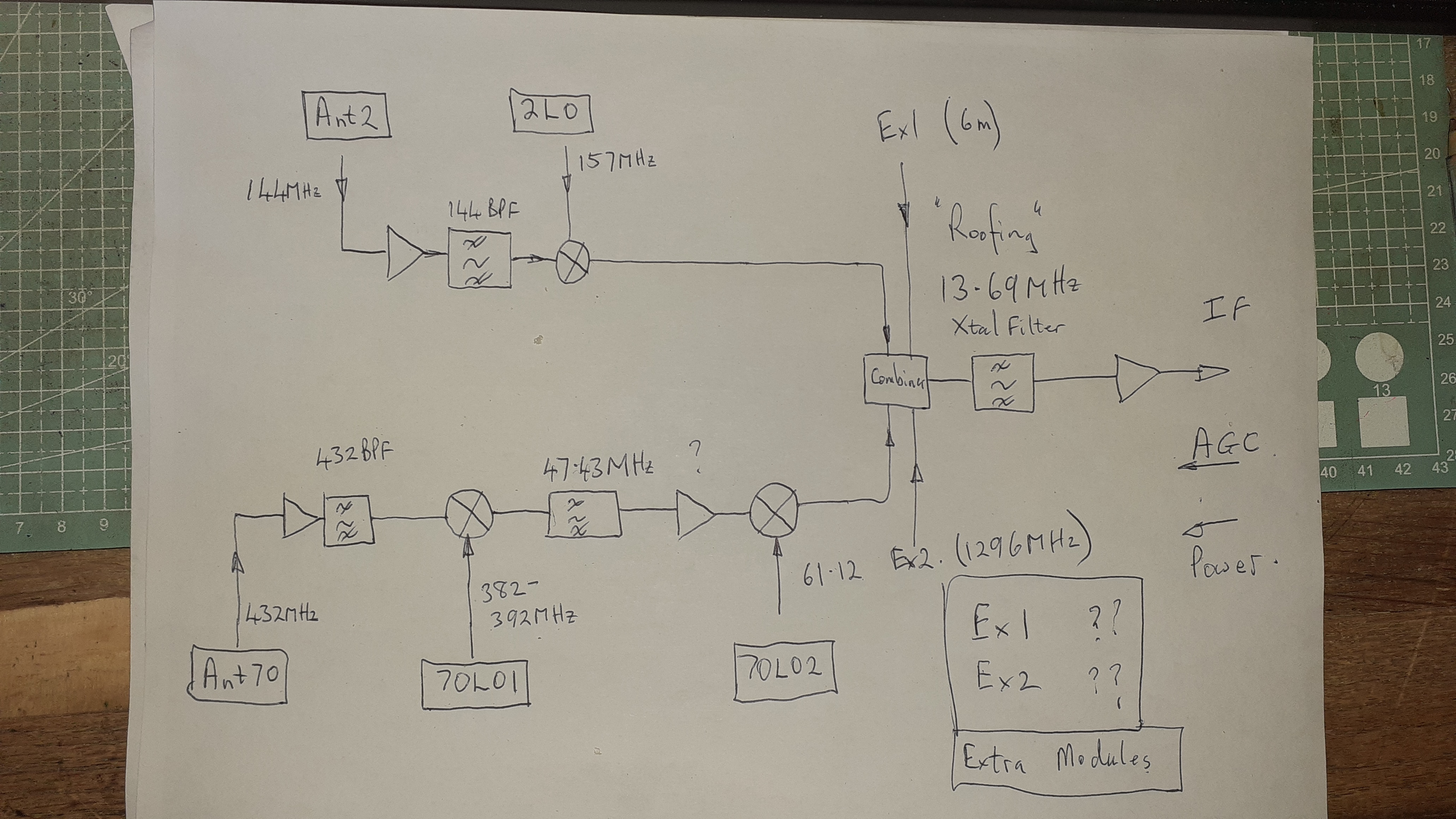
This is a block diagram of the replacement board(s) traced out from examination of the PCB.
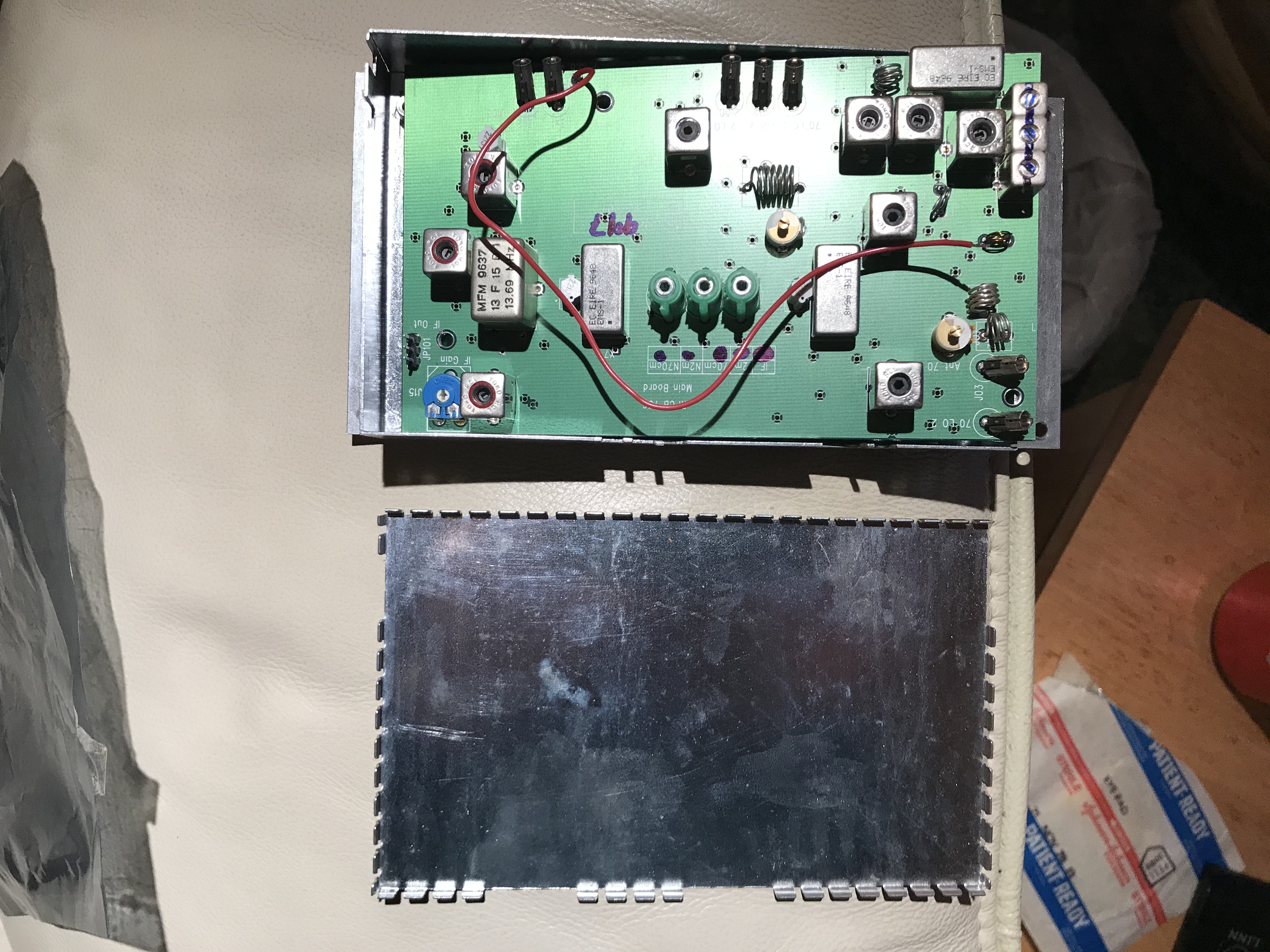
The replacement IF PCB with the screening enclosure.
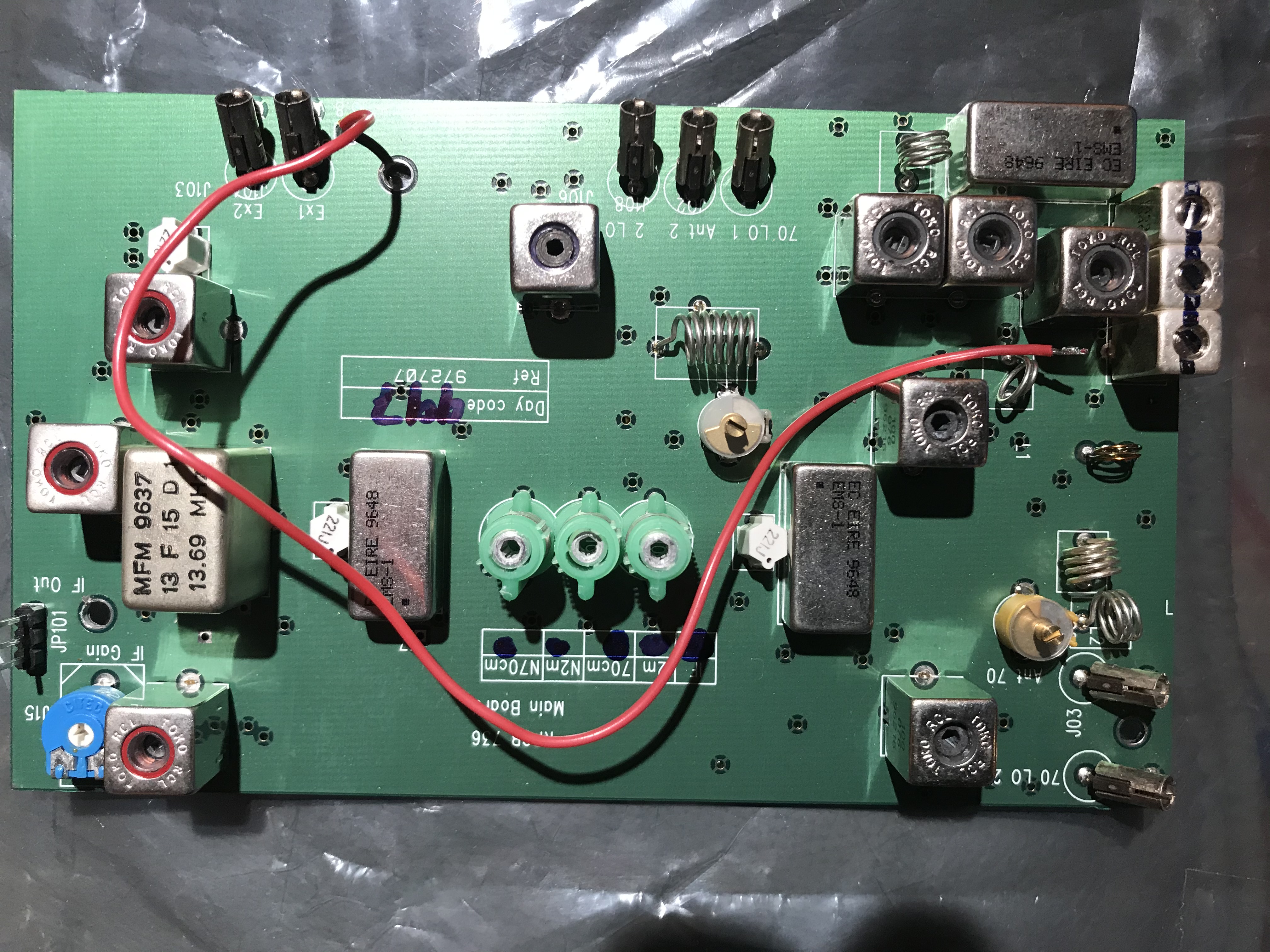
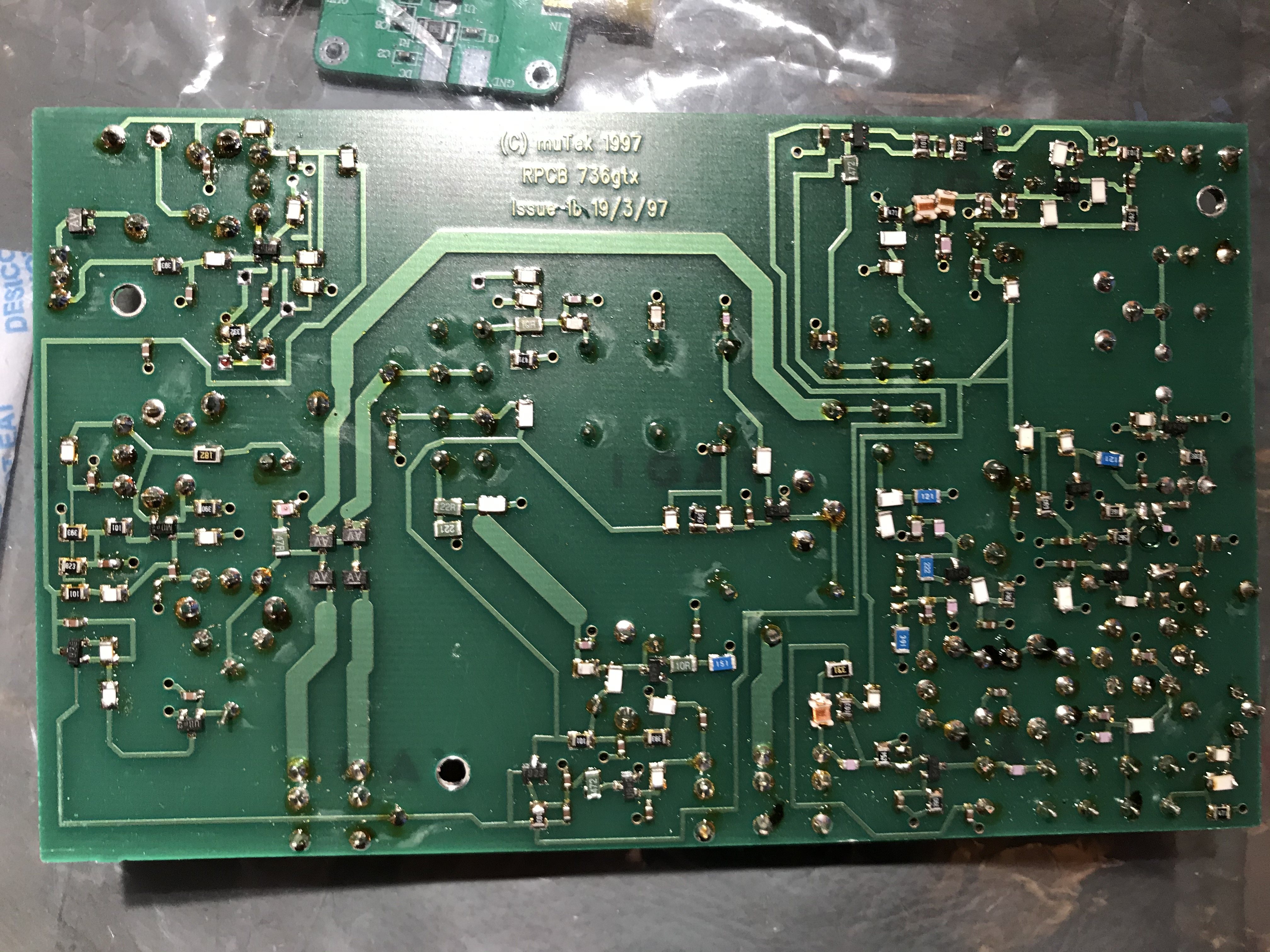
Close-ups of the IF PCB.
Front-end improvement
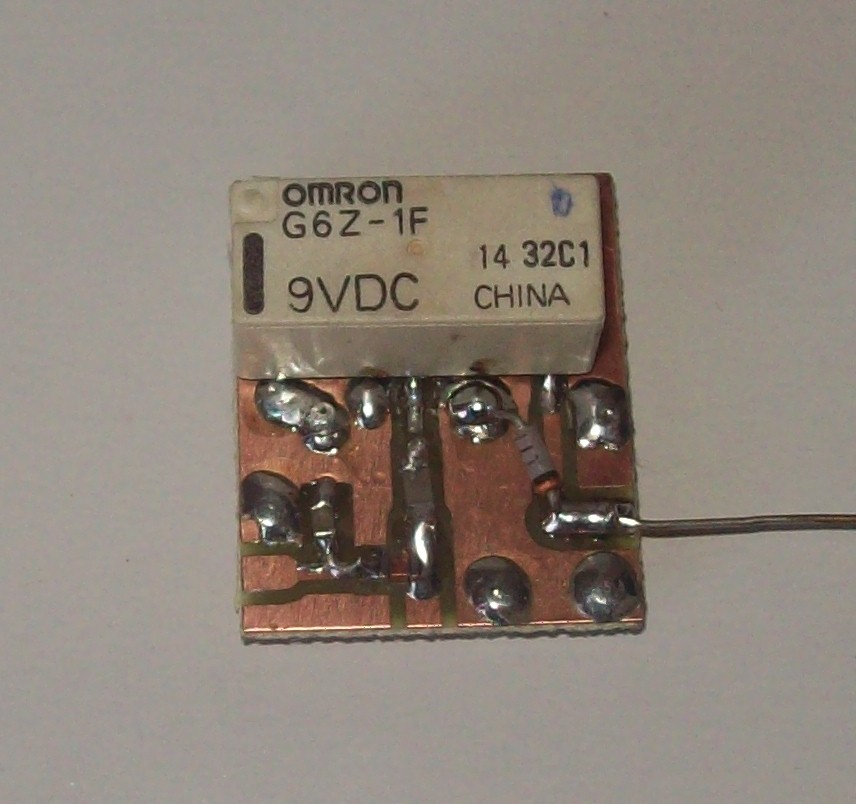
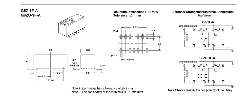
I do not have pictures of the two RF front-end PCBs but these are simply to replace the existing front-end circuitry with a low-noise pre-amp and a mechanical relay. The original Yaesu boards used PIN diode switching which was somewhat lossy, degrading the noise performance. In my 736 I replaced the PIN switching with an Omron G6Z-1F 9V SMD RF relay on 2m and 70 cm. This improved the sensitivity, NF and power output. The relay PCB I used is below. This NF on 70 cm went from around 10dB down to around 2dB. The original NEC GaAs FET is quite a respectable device.
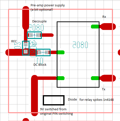
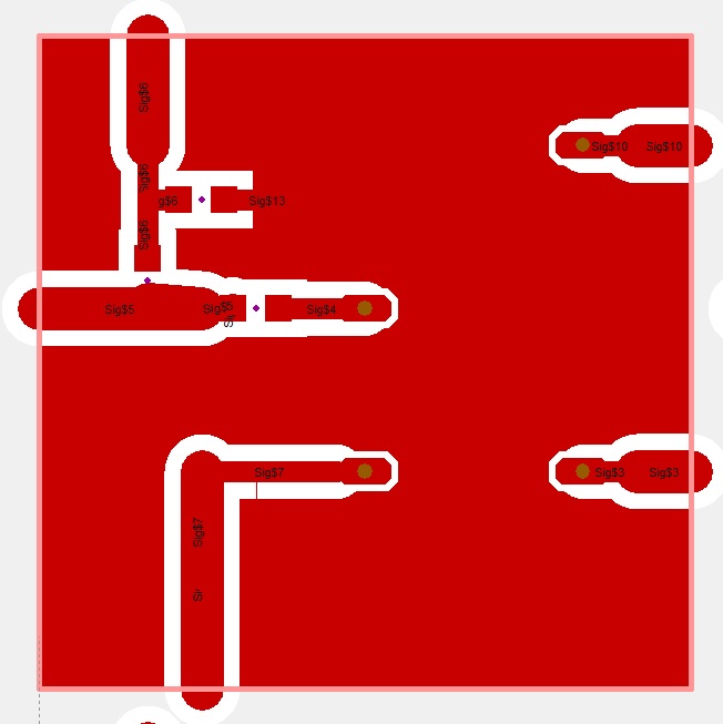
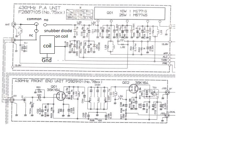
Below is a (rather poor) schematic showing the circuitry for the relay replacement on one of the VHF/UHF front-end PCBs The 144 and 432 MHz front-ends use the same PCB layout.
I should add that my 736R still does not have a Mutek upgrade. Back when I bought mine the kits were around £600-700 and having spent £950 on a second hand radio with 50 MHz and 23 cm I considered it expensive. I have considered trying to "homebrew" one. The components are all readily available apart from a suitable 13.69 MHz crystal roofing filter. Anyone know of a good source of filters ?? Eliminating the PIN switching improved the sensitivity on both the VHF and UHF sections. The 23cms optional module uses relay switching so that was left alone. I have not invesitgated the 6 m front-end. Locally the noise level is so high it probably wont make a difference.
Brian GM8BJF
5 Jan 2021.