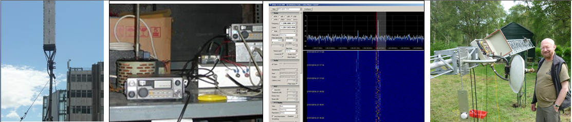
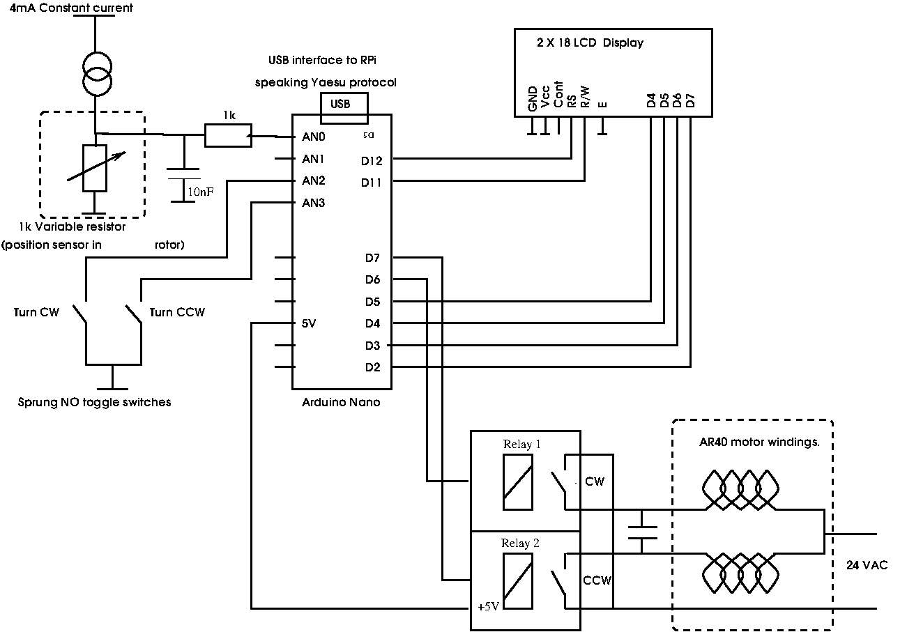
Over the course of the last year I have building up a remote station primarily for VHF and have arranged that a 2m Yagi can be rotated remotely. For this I used the excellent K3NG arduino rotator control software as described here. To point the Yagi I used the CDE AR40 rotator which was already installed. This has two windings, one to turn clockwise and one for anti-clockwise. To make the rotator rotate one or other winding is energised by a pair of relays.
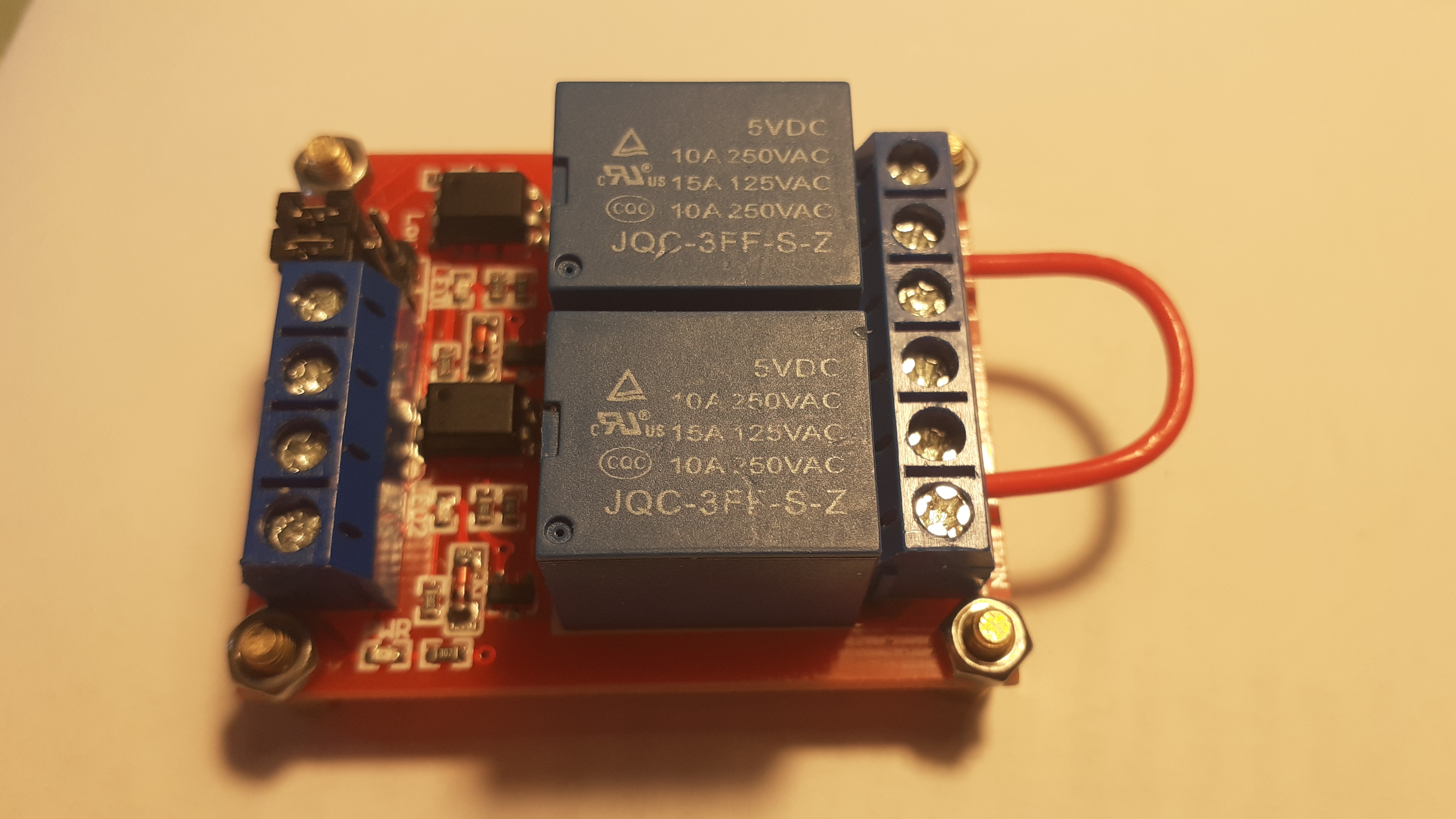
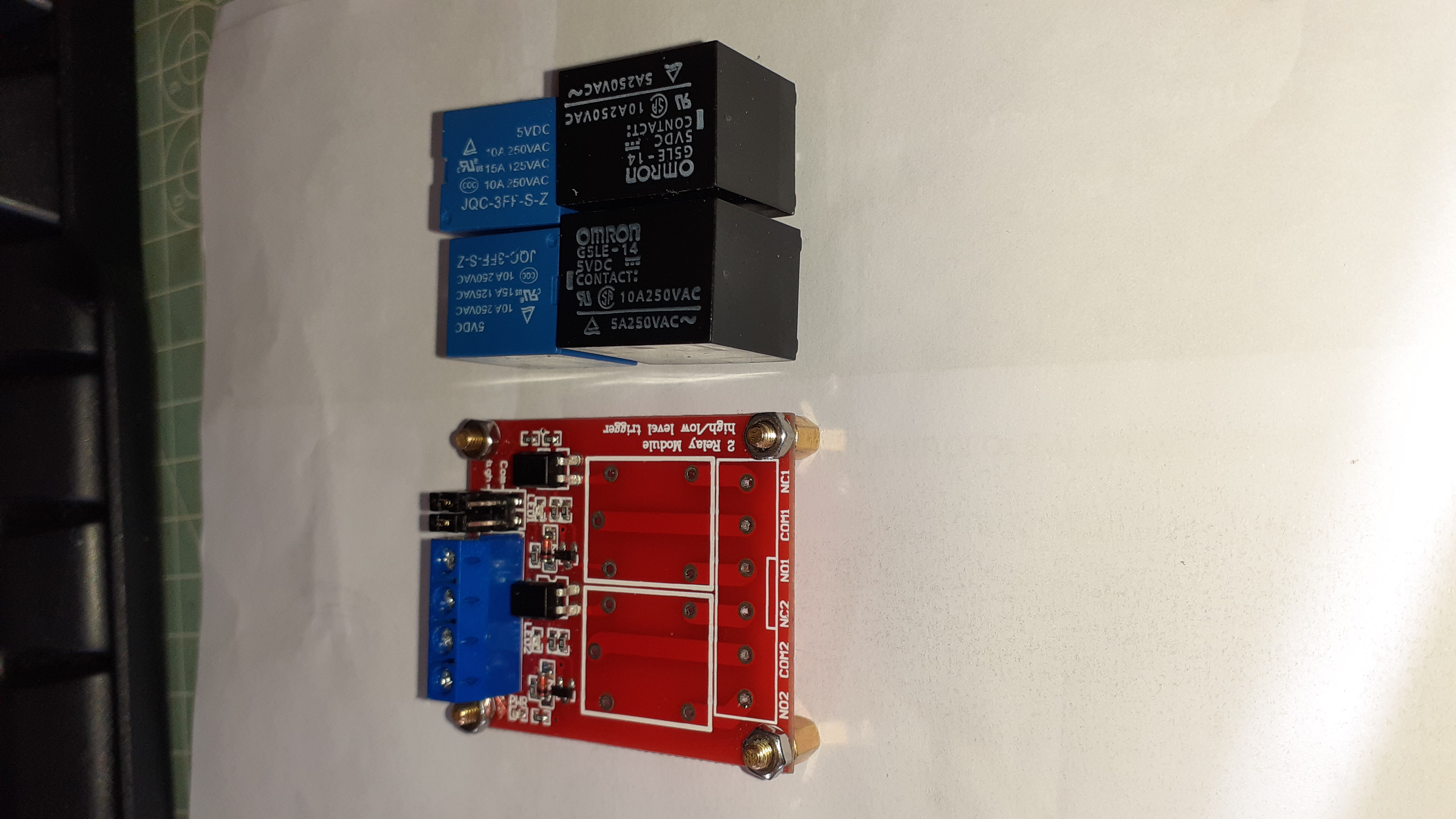
For this I used one of the two-relay modules which are widely available on Ebay and similar sites which is shown below. These are nicely constructed on a glass fibre PCB and include an opto-isolator to protect and isolate the Anduino from the load circuit. The rotator draws about 4 A when turning and the rating on the relay casing suggests it can handle 15A when switching 125 VAC so the module seemed to be conservatively rated for this application.
This module worked fine for around 3 months but started to show problems after the proper CDE motor start/run capacitor was fitted. The issue was that the contacts started to stick (weld!) together in the "on" position when the relays were operated. Eventually both contacts welded in the "on" position keeping both forward and reverse windings simultaneously energised. Initially I did not realise this had happened and the result was that the toroidal mains transformer I was using to supply around 20 Vac to the rotator failed when its primary went open circuit. Needless to say this happened when I was at the remote end of the link. On the next visit to the remote site I was able to diagnose the fault when I found that both sets of contact were stuck closed which was alarming.
Fortunately the good old CDE rotator seems to have survived.
I removed the module from the unit and in the process of moving it about the contacts freed themselves. As I had already had another of these relays fail in another project I opened one of them by carefully cutting off the case with a Dremel-type tool. On initial inspection the contacts look quite substantial being about 4mm in diameter.
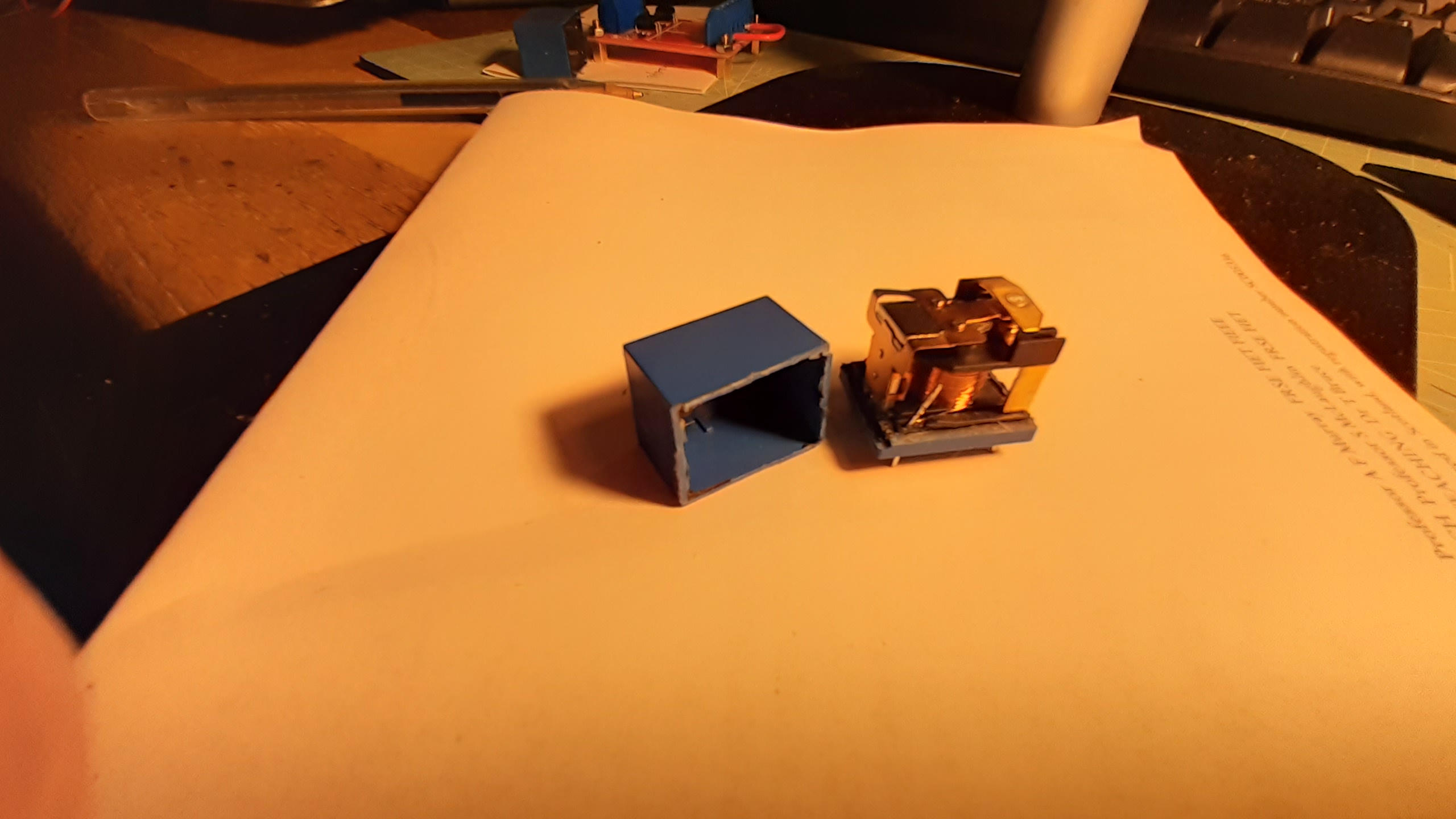
Closer inspection of the contacts was carried out by bending the top one and the movable contact out of the way and the bottom contact was seen to be badly pitted and burnt looking as shown below.
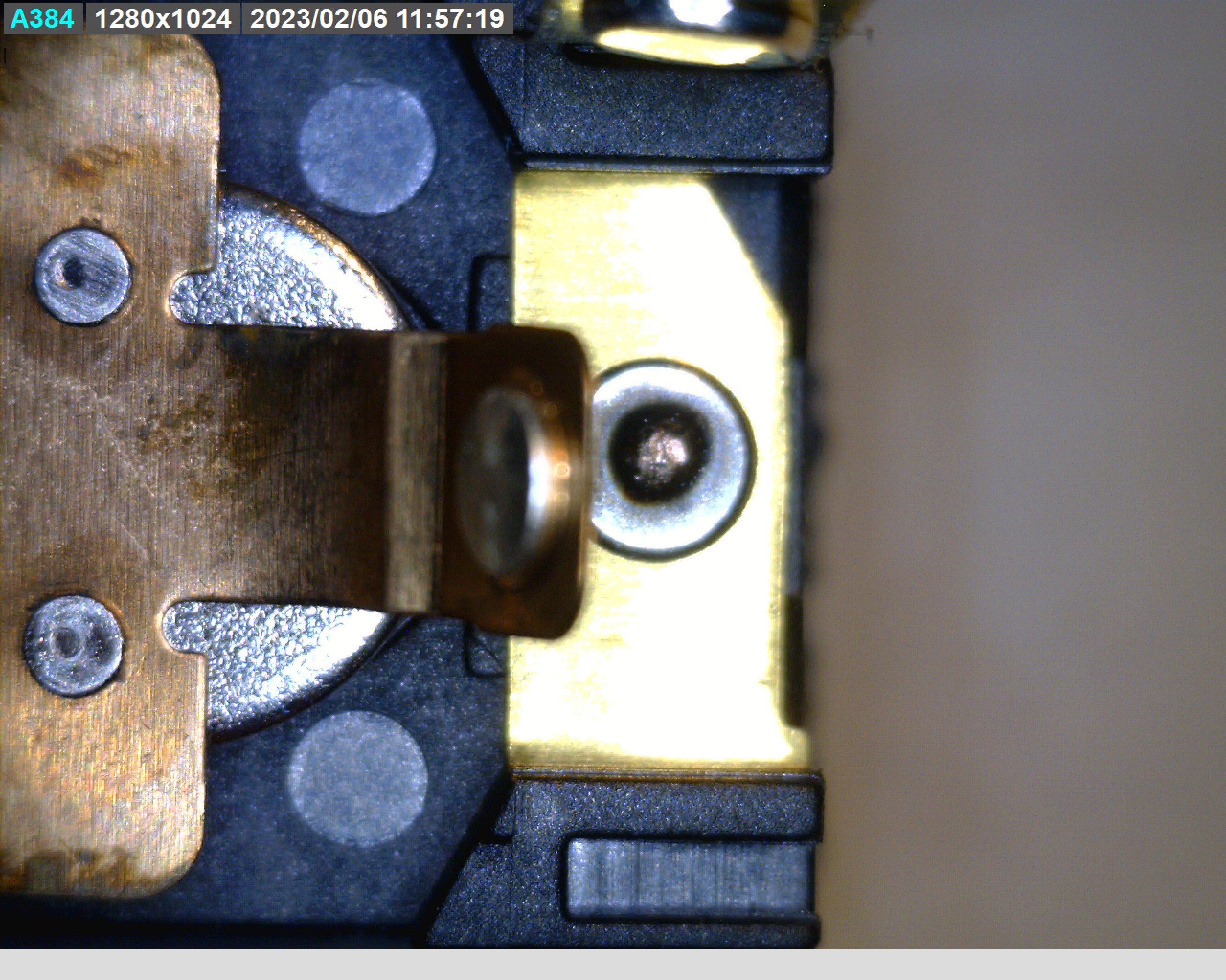
Clearly the ratings printed on the case are considerably over-stated and while the physical size of the contact looks adequate they are made of some inferior material. One can only assume that the relay designers have, whether for reasons of cost or ignorance, got the metallurgy of the contacts wrong! Good quality relays normally use some refractory metal for the contact which resists this kind of damage and failure.
The relays in my unit are not marked with a makers name or trademark but on further research on the internet I read that even ones that show a manufacturers markings such as Songle and Tong Ling exhibit the same failings as described here.
I found that Omron, a well established and respected maker of relays, have a product with a similar package size (only marginally larger) that can be fitted to the PCB without altering the board. The part number is G5LE-14-DC5. It is rated for 10A at 250VAC. The datasheet is here.
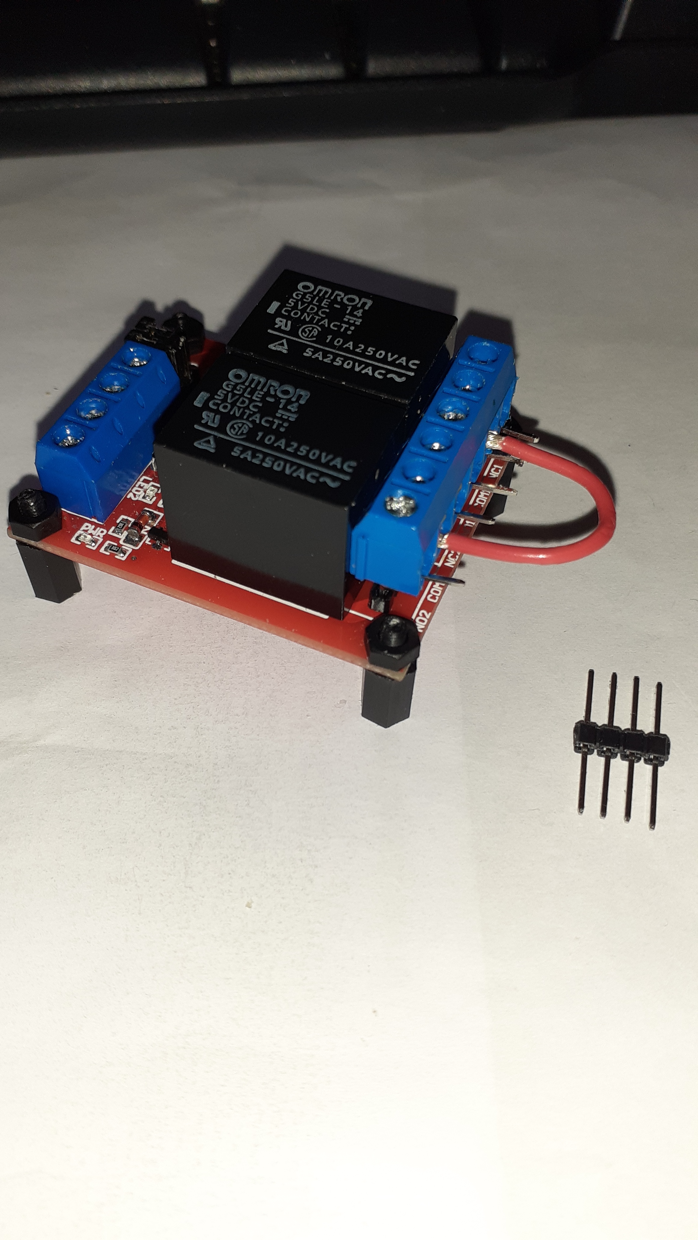
The Omron parts have the same pin footprint but the case dimensions were slightly larger. They fit onto the board but the screw terminal block had to be removed. Connection was effected using some header pins, shown in the final photo, which allowed the terminal block to be reconnected.
The moral of the story is that you get what you pay for !! Hopefully the will be no more welded contact issues
February 2023.