Introduction
Recently I have been living away from my main station in noisy, low lying urban location which unlike my main station is a poor location for operating radio. The obvious solution to this was to run my main station remotely. This article describes how I achieved this using open source, freely available software packages and an Icom IC706 Mk2 G.
I was already familiar with the Raspberry Pi (RPi) series of computers and their headless operation with the remote desktop package RealVNC. This package is made available for free home use on the Raspberry Pi by the vendor and allows the remote operation of a RPi running what ever software you wish. It comes installed as part of all recent RPi software distros and the server only has to be enabled in the interfaces tab of the RPi configuration tool. To control the RPi all that is required is a client computer, typically a Windows PC, that is running the RealVNC client software, sometimes referred to as the viewer.
Transceiver control software
For the operation of the transceiver I chose to use FLRIG which is an open source cross-platform package. It is available as a precompiled binary on the RPi software repository but if you want the very latest version it is available from W1HKJ 's website and supports a very wide range of different transceivers, including my IC706 Mk2 G. Jason, KM4ACK gives an excellent tutorial on Youtube on how to do this. It has a nice simple GUI which allows mouse control of a transceiver.
Transceiver control interface
For the control interface I chose to build my own but it is perfectly possible to use a commercial unit such as the Signalink or Rigblaster types. A block diagram of my homebrew unit is below. I found it was important to incorporate 1:1 audio isolating transformenrs to avoid noise on the transmit audio.
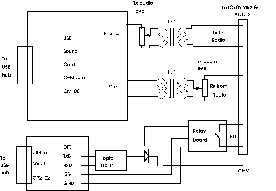
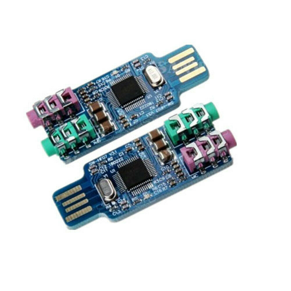
For the audio side I used a C-Media CM108 USB sound card. These are available on Ebay at low cost and work well in this application. the one I used is puctured below.
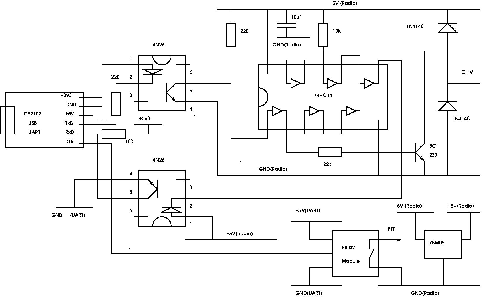
I also added opto-isolators to the CI-V interface to break hum loops and minimise the opportunities for RF inductive pick-up especially on the HF bands. Details of the isolated control interface are below. The circuitry on the right of the 4N26 opto-isolators is powered from the +8V pin on the IC706 13 pin ACC DIN socket.
I also built the whole of the control interface into a well shielded box with a good filtered IEC mains power connector.
As another general point I strongly recommend that you use a powered USB hub to connect the USB peripherals to the RPi. I have found that in general if you draw too much current from the USB ports on the RPi it can result in unreliable behaviour. For remote operation the last thing you want is a crashed RPi at the remote end requiring a power cycle to reset it.
The audio link
In order to use the radio it is necessary to pass the receive and transmit audio over the internet link. This in some respects was the toughest bit of the project to get working well and there are some observations later in this article about this process. For this task I used a package called MUMBLE. This is a package intended for computer gamers to discuss game strategy while playing games. It gives two way duplex audio transmission and can be made to work well in this application. It operates in a simal way to RealVNC in that the Mumble server (MURMER) runs on the RPi and the client on the remote computer. Again it is cross platform and can be downloaded from the RPi repositaries. There is a Windows MUMBLE clent which runs on the client PC. MUMBLE provides a number of digtal signal processing (DSP) functions but I found they do not play well with white noise and are best switched off or minimised in this appication. A useful and detailed tutorial on setting up MUMBLE for a remote station by Jason, KM4ACK is here on Youtube.
I found the audio link was the most difficult part of the project to set up and get working in a satisfactory way. I strongly recommend that when doing the initial set up you have access to both ends of the link so that you can measure the audio levels at the different stages, This was caused in part by the fact that the line audio levels on most amateur transcievers are not well defined or specified and best measured initially by feeding an audio signal generator into the line input to determing how it behaves. once you know how much signal is required to operate the transmitter properly you are then 90% of the way there!
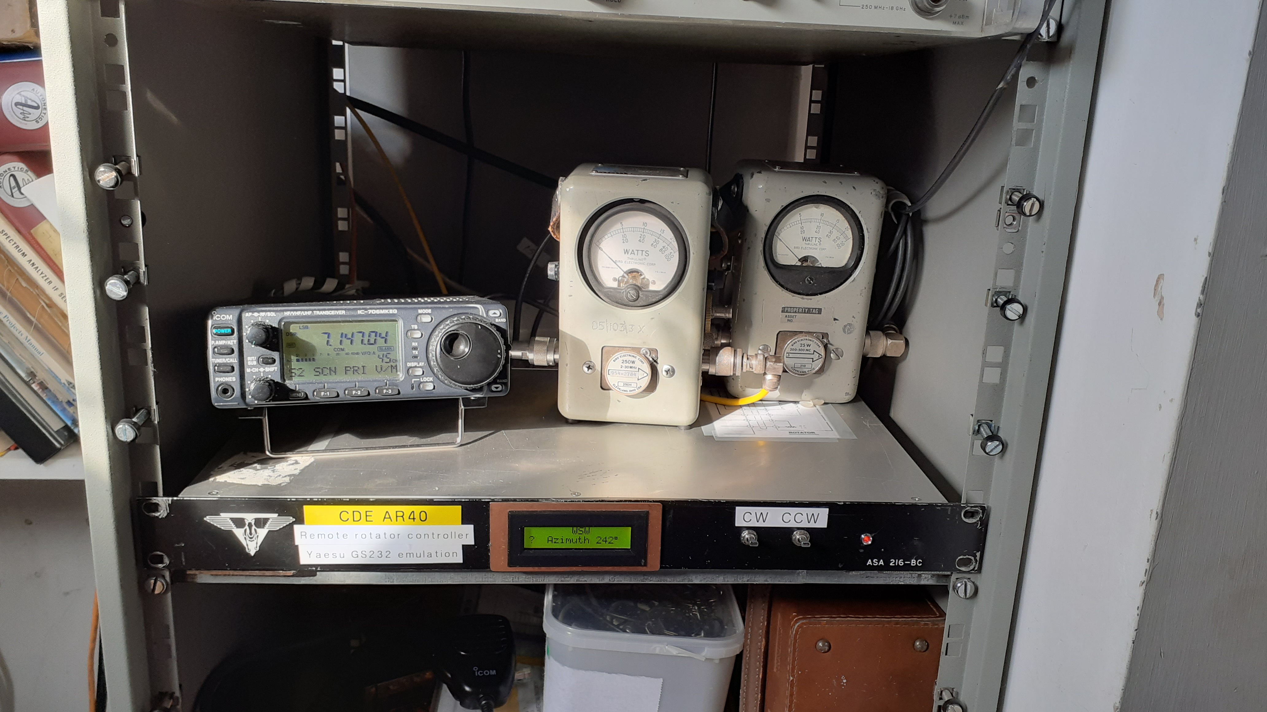
Remote antenna rotation
Once the basic radio remote functionality was established attention turned to pointing the 2m horiziontaly polarised Yagi remotely. The rotor in use is a venerable CDE AR40 which is turned either clockwise or anticlockwise by 24 volt capacitor start AC motor. The position is sensed by a 1 kOhm wirewound variable resistor. To control the antenna position a hardware interface to the RPi and suitable software were required. A search of the internet revealed the excellent K3NG Rotator Controller package on Github.This is a very versatile package that allows the position control of antennas by means of an Arduino microcontroller. To control the AR40 only azimuth control is needed and an Arduino Nano was quite adequate for the task. The package is setup by means of a configuration file for the particulat requirements of the rotor and the interfaces required. In this case the arduino was programmed to emulate a Yaesu GS-232A rotor controller. This meant that by making the RPi send and receive GS-232A commands it could turn the antenna to a desired angle and read out the position from the 1k variable resistor in the rotor. Running a terminal emulator on the RPi allowed commands to be typed to rotate the rotor both clockwise and anticlockwise as well as reading its current position. Later a GUI programme Pyrotor was found which presents a compass rose azimuth display on the RPi. desktop. Pyrotor was written in Python by David Fanin and is available here. It is a GUI for the rotctl/hamlib antenna rotor control program rotctl and is designed to work with the K3NG antenna rotor controller software.
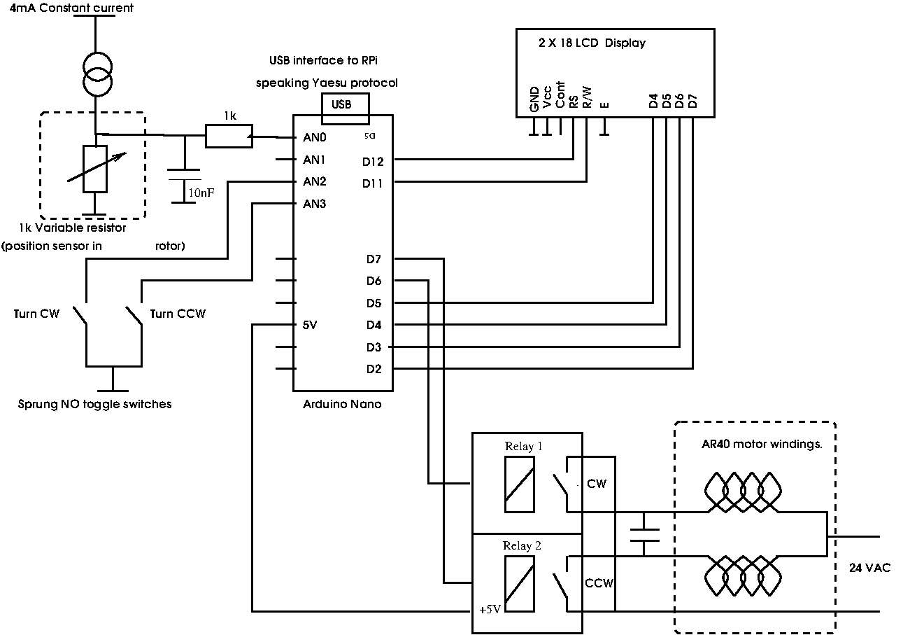
The configuration file, rotator_features.h , for compiling the software that I used for my setup is here..
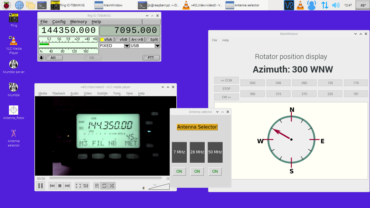
Remote station desktop
The dsktop on the RPi is shown below. All of the functions that can be controolled over the CI-V interface are available on the FLRIG window. The Pyrotor interface can also be seen. The CW and CCW rotation can be selected and manuallys halted when the desired direction is displayed. An image of the front panel of the radio has proved useful for debugging problems and monitoring the transmit output which is not available from the IC706 over its CI-V interface. A simple GUI also allows the selection of different antennas by means of a three way rotary coax switch.
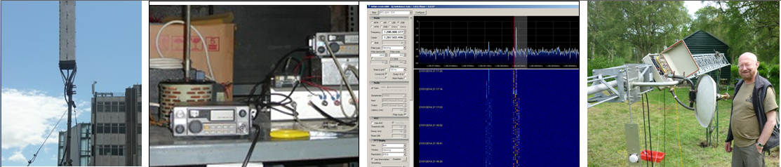
An overall block diagram of the controller is shown below alonw with a picture of my installation.
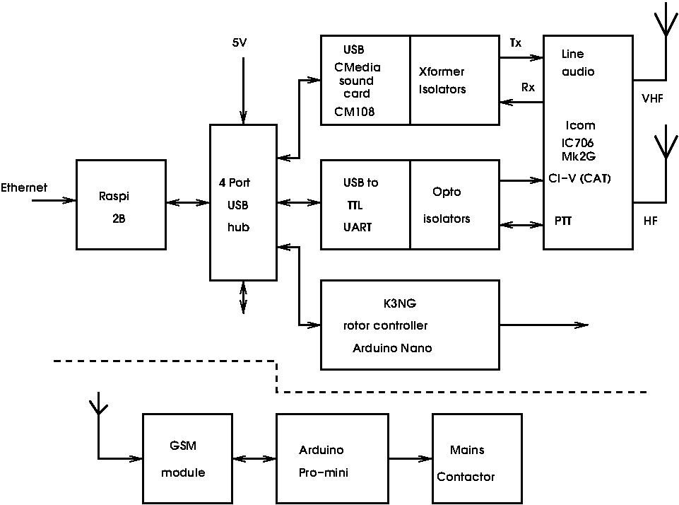
I also felt that it was wise to have overall control of the station via the phone system and added a phone link so that the staion could be powered down remotely independent of internet access. This is described below.
Remote power switching.
It was considered that it was useful to be able turn power to the whole setup off and on remotely. This provides a means of software crashes and means the station can be turned off when not in use. Small GSM cell phone modules are a available at very reasonable cost on Ebay. These are either based on the SIM800L Ublox module or the Neoway M590E module. I chose to use the Neoway module. These come as a small kit consisting of a PCB an M590E, a SIM card holder and a few SMD parts. The M590E module had clearly been recovered from some scrapped equipment but were found to work well. Combined with an Arduino and a SIM card these make a useful teleswitch. I used an O2 pay as you go SIM card in the setup. This cost 2 pence per text message and so a £10 top-up goes a long way!! Provided the SIM is used regularly the credit does not expire. The code I used is based on code on Github . My modified code is here. Pictures of the Teleswitch unit are below.
M590E Kit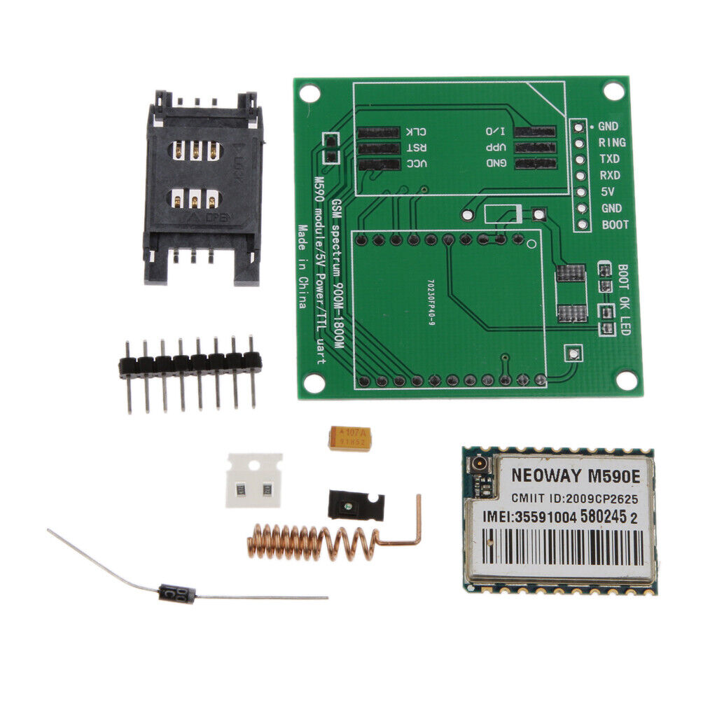
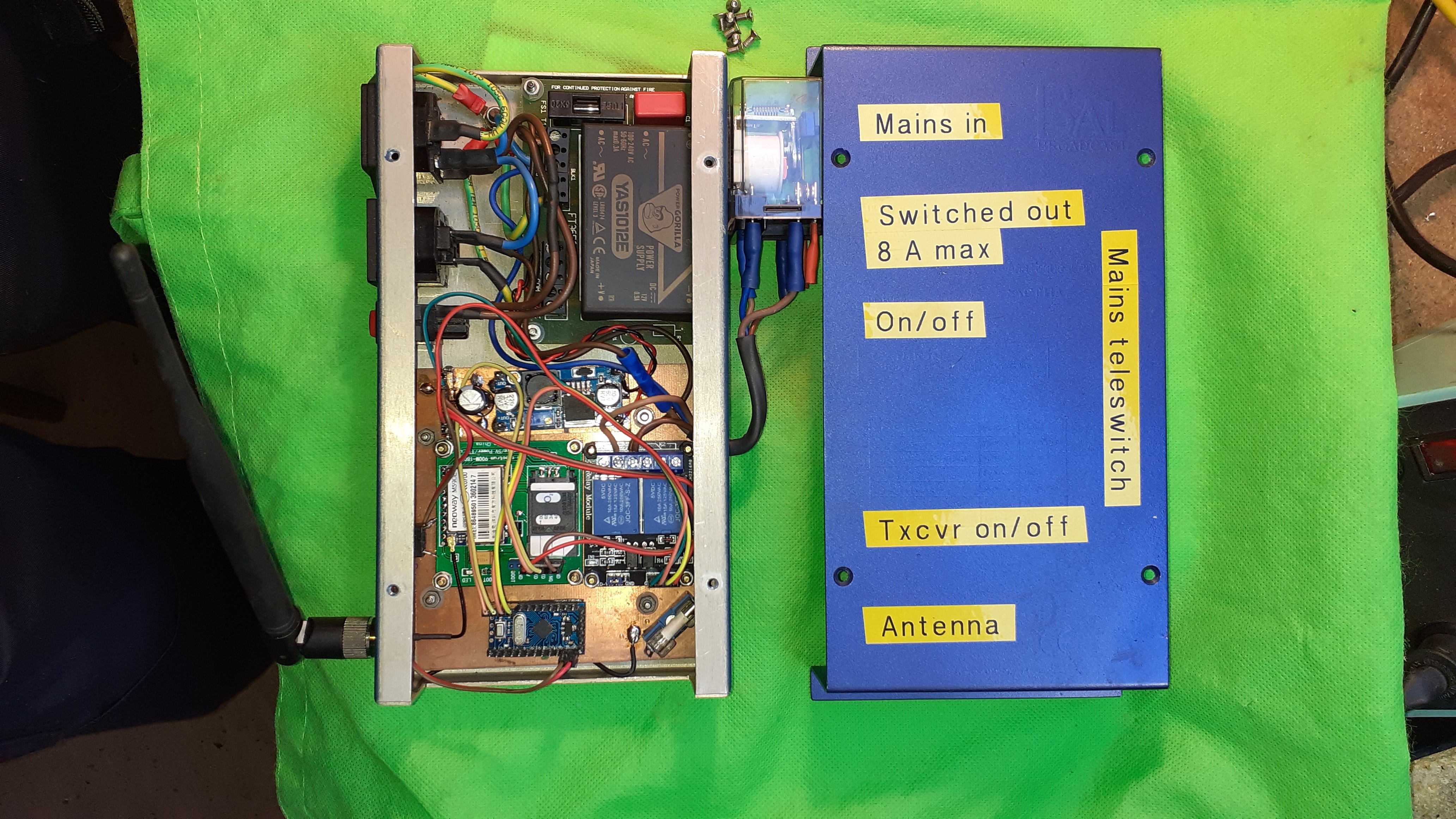
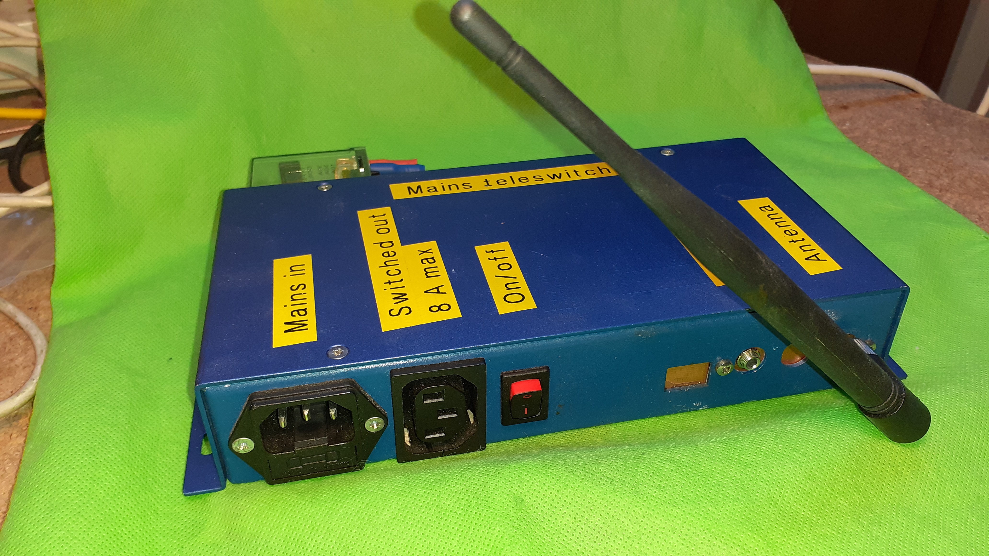
front panel
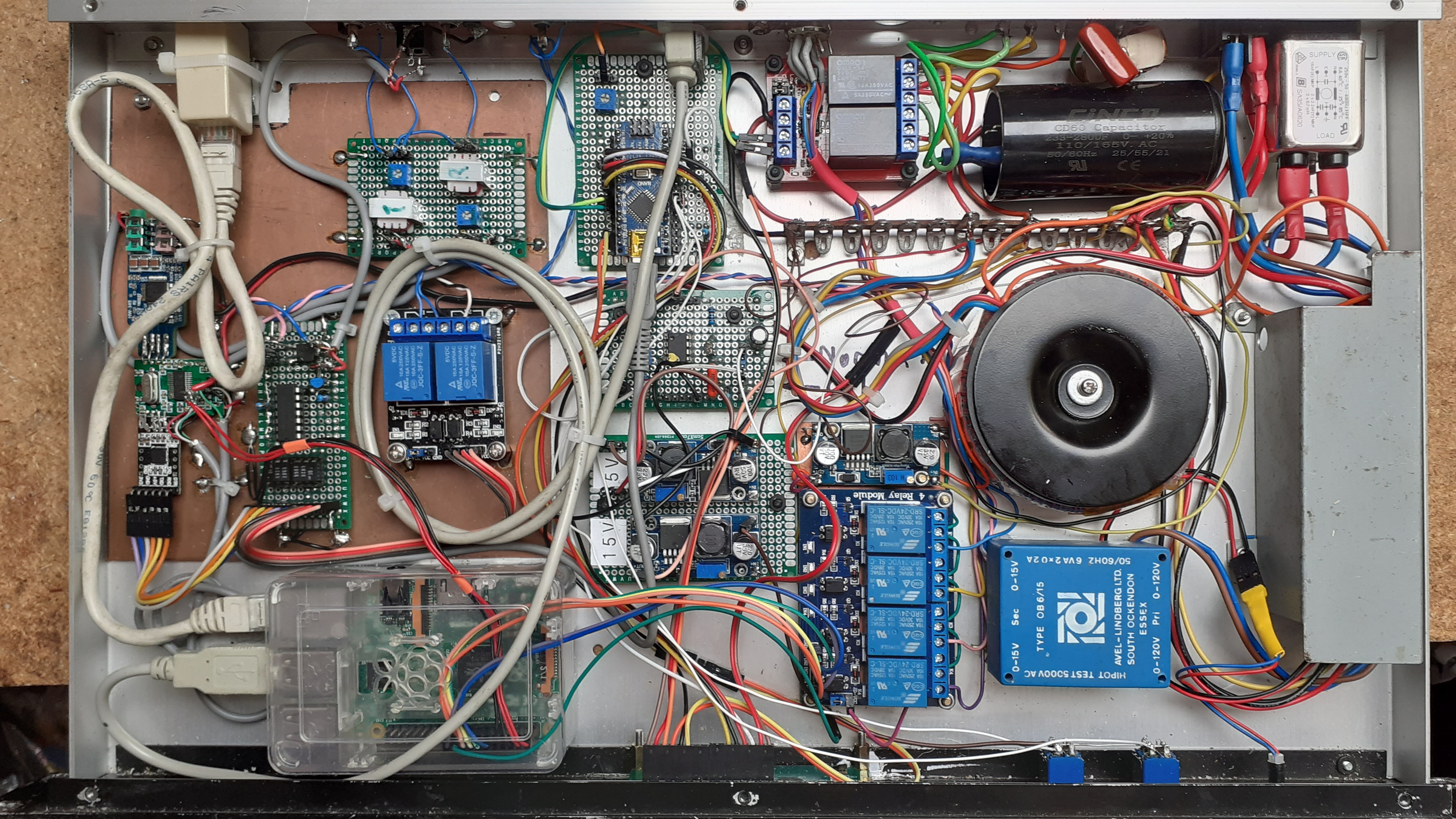
The overal installation.
The entrails of the controller box in November 2022.
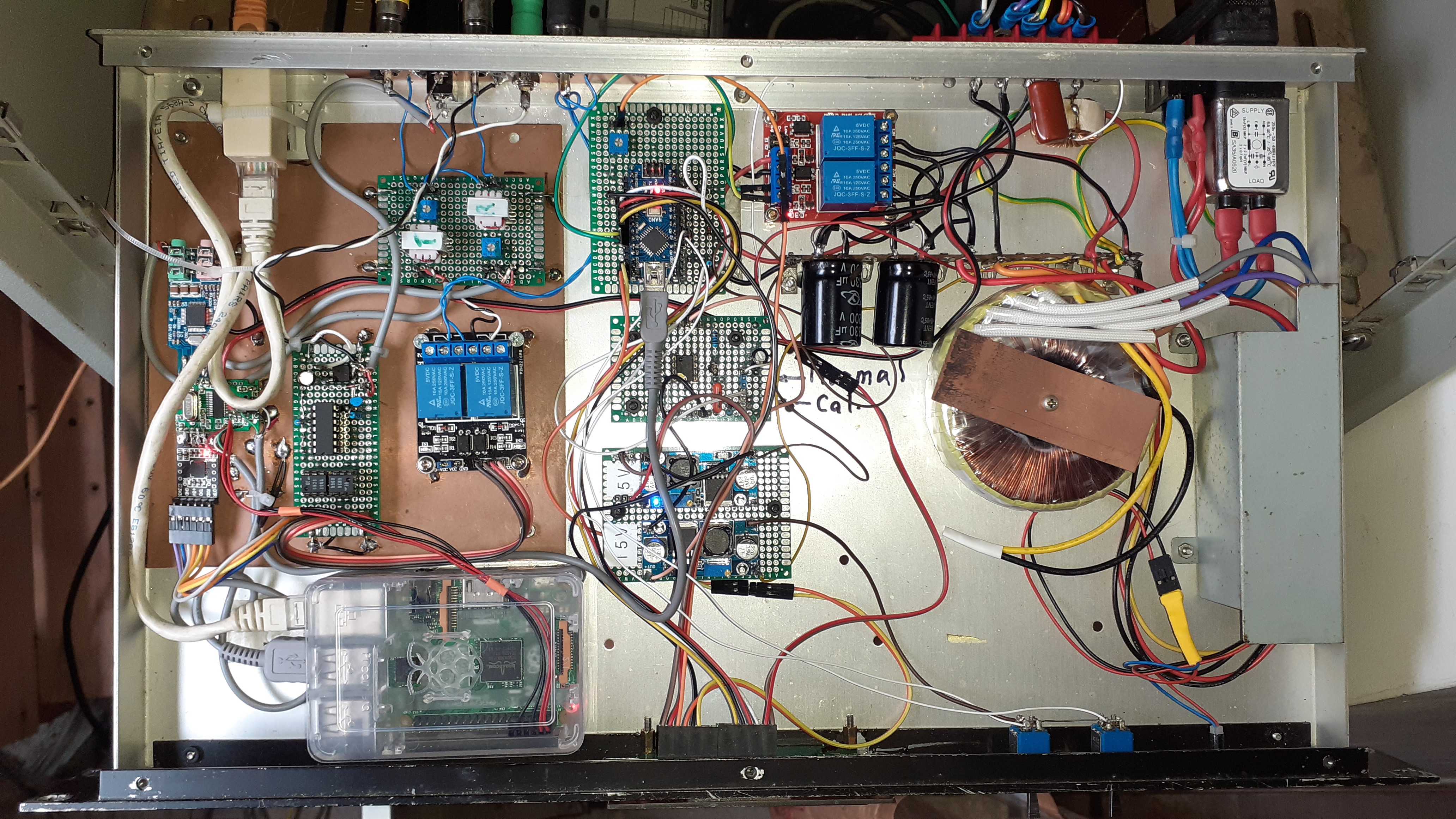
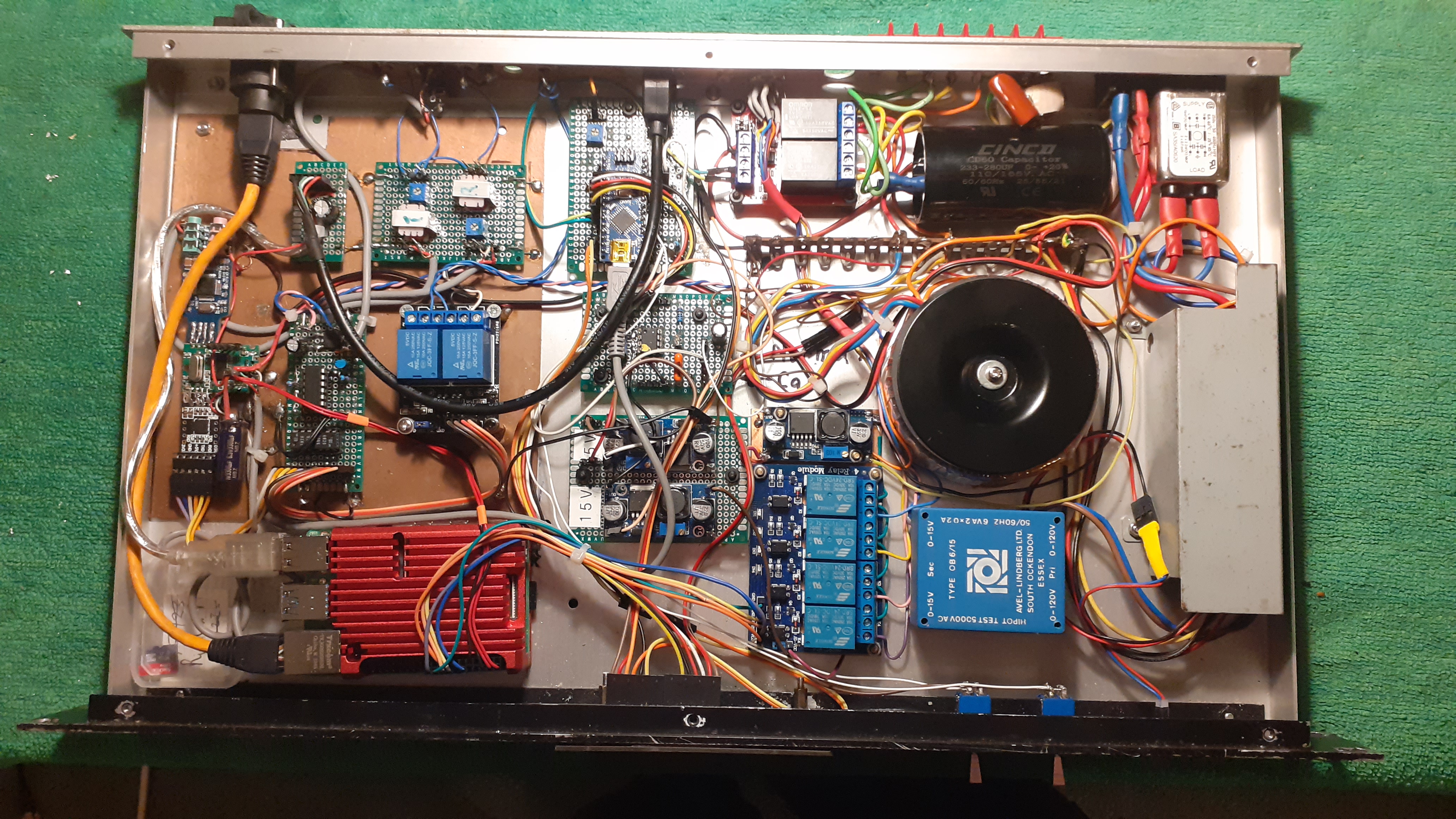
The Controller box in May 2023. Recent additions include four relays to cpulse a three way rotary coax switch for selection of different antennas. This is effected by means of GUI produced with a Python script running on the Raspberry Pi. An interface for a webcam has also been added to connecdt a webcam directed at the front of the IC706 to monitor the transmited output signal. This overcomes the inability of the '706 to give an indication of output power on its CI-V interface.
In 2022 gave a talk at our local radio club describing the development of my remote set-up. The slides are here.
Recently ( October 2023) I have been tidying up the wiring to some small extent and fitting some proper panel mount connectors to the back of the casing. This makes it easier to connect and disconnect the unit from the rack where it normally lives. These pictures are useful to me to keep a recond of the mods I have made to the unit as obviously I do not have normal access to the hardware! the latest picture for teh record is below.
Acknowledgements
- RealVNC for making remote desktop available.
- David Freese, W1HKJ for Flrig.
- Anthony Good, K3NG for Arduino Rotator Controller
- David Fanin, KK6DF for Pyrotor
- Jason A Oleham, KM4ACK, Various useful Youtube videos on setting up Mumble for radio applications. -Link