Recently I noticed that the sensitivity of my much prized HP 141T/8555A spectrum analyser had dropped rather drastically. I feared that the input diode had died for some reason and a d.c. check of the mixer diode, as described in the service manual [1.], confirmed my worst fears. The diode was short circuit.
After a period of dejection I considered methods of repair. The first mixer is a thin film microcircuit which HP replace as a unit of it is damaged. There is also a small plug-in PCB assembly which contains select-on-test resistors, used to set the mixer bias and the 50MHz IF amplifier gain, to define the calibration of the unit. This PCB is changed along with the mixer. Deciding that there was little to loose I removed the lid from the mixer package. The mixer substrate is housed in a gold-plated metal case with a lid which is held in place with conducting epoxy adhesive. The lid can be removed by carefully prizing it off using a small screwdriver as a chisel while holding the mixer unit in a vice.
This revealed the circuitry on the substrate shown in Figure 1 below.
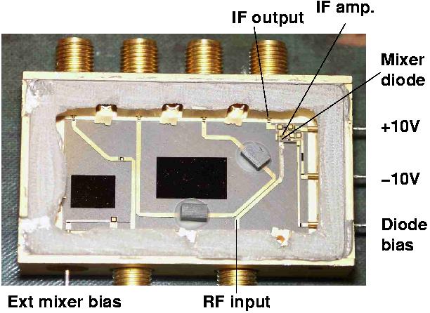
Figure 1
The mixer diode is a chip device which is bonded to the substrate and the post mixer amplifier is a grounded base bipolar silicon transistor. The mixer diode output drives directly into the emitter of this transistor, presumably to give a good broad-band match to the mixer diode output impedance.
Initial attempts to replace only the mixer diode with a surface mount packaged device were unsuccessful. For this to succeed wire bonding facilities would be necessary. The next attempt was to replace all of the active circuitry as per the simplified circuit diagram shown in Figure 8-12 of the service manual. This was not very successful as the sensitivity dropped drastically.
The alternative approach adopted was to replace all of the active circuitry with the circuit shown in Figure 2 fabricated with surface mount components. The first step was to ground the two common leads to the ERA2 to the earth point on the substrate. This was achieved by careful soldering with a fine bit. Once the ERA2 was in place the bond wires to the package connections were broken so that connection could be made to them.

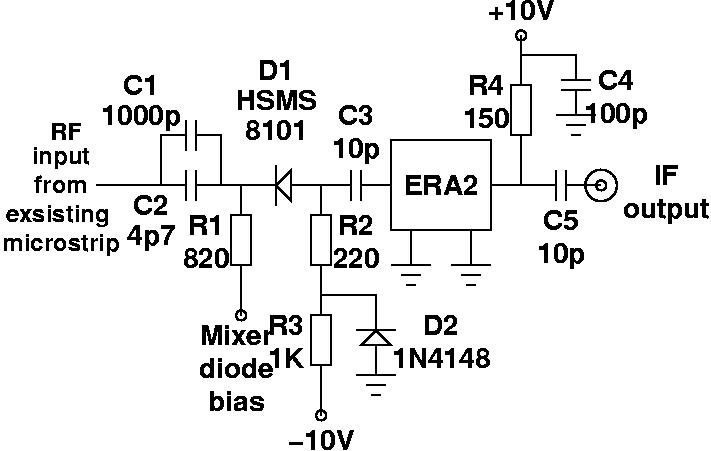
Figure 2
The ERA2 amplifier operates as a IF 2GHz pre-amplifier and provides a 50 ohm termination for the mixer diode. The HSMS-8101 is a Schottky barrier mixer diode which is available from Farnell. The capacitors C1 and C2 could be omitted if use can be made of the existing component mounted on the input microstrip. Attempts to solder to it were unsuccessful and resulted in its destruction, hence the use of C1 and C2. These were paralleled to give a broad band capacitor as the instrument operates from 10 MHz to 18GHz. It would be preferable to retain the original part in circuit to maintain the response of the instrument at the lower frequency end of its range. The resulting modified mixer is shown in Figure 3 below. The result is not pretty, but it meant that the unit became usable again, (even if HP/Agilent would not approve of the accuracy!). The ground connections to C4 and D2 were made directly to the metal case with conducting epoxy. They were first soldered in place, in contact with the case, using the solder connections to locate them. The ground connections were then formed with sparing "blobs" of conducting epoxy.
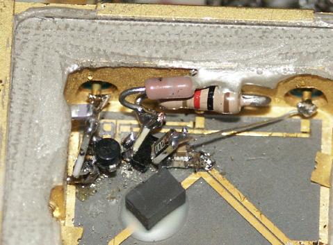
Figure 3
Mixer Bias
The mixer is operated as a harmonic mixer to get the wide tuning range. It operates up to the fourth harmonic of the 2 - 4 GHz YIG LO. To optimise the conversion loss the dc bias applied to the diode is set for each harmonic. This is controlled by fixed resistors mounted on the daughter board assembly A10, which is mounted on plug-in board A6. Experimentation with the resistor values can improve the sensitivity. This was achieved by temporarily replacing the appropriate resistor with a 4k7 variable and varying it for best sensitivity on a suitable signal and then re-fitting a suitable fixed resistor.
Performance
The repaired mixer gave reasonable performance over the full range of the instrument. The amplitude calibration is not as good as it once was, but is within 2-3 dB on all ranges. To complete the calibration the resistors controlling the IF amp gain on the A16 assembly would repay attention. When time permits these will receive attention. After testing the lid was replaced using more conducting epoxy.
Conclusions
This procedure was able to bring an otherwise useless piece of equipment back to life and allow it to be useful for amateur work. Manuals for the 141T mainframe and most of the plug-ins can be downloaded from the website: https://www.logsa.army.mil/etms/online.htm and for those of a squeamish disposition can also be found at: http://bama.edebris.com/manuals/hp/
The full operation and service manuals for the other 141T plug-ins, preselectors and tracking generators are available. There are also manuals for other items of test equipment available if you search the site. Be warned they are large files!
Reference
-
Spectrum Analyser RF Section 8555A, Operating and Service Manual. Hewlett-Packard Company, Santa Rosa, USA, 1971.
Acknowledgments
The author wishes to thank Peter, GM4DTH for taking the photographs.
|
Parts listing |
|||
|
R1 |
820 |
0805 |
|
|
R2 |
1k |
1/8W axial |
|
|
R3 |
220 |
0805 |
|
|
R4 |
150 |
1W surface mount |
Farnell 507-878 |
|
C1 |
1000p |
chip |
|
|
C2 |
4p7 |
ATC100A |
|
|
C3 |
10p |
chip |
|
|
C4 |
100p |
chip |
|
|
C5 |
10p |
chip |
|
|
D1 |
HSMS8101 |
Farnell 994-649 |
|
|
D2 |
1N4148 |
||
|
IC1 |
ERA2 |
Mini-Circuits |
|
Updated 18th November 2005