Back in the 2013 I was visiting my friend and near neighbour Briain Wilson, GM8PKL, who has a very good view from his from living-room and patio to the north over the City of Edinburgh and beyond. He told me that on very clear winter days he could see snow covered peaks which he thought were in the Cairngorms which are at a distance of around 140km away. A few weeks later I was visiting Chris Tran GM3WOJ (a well known HF DXer/contester) who lives near Tain in Ross and Cormarty and he happened to remark that from his patio he could see Ben Macdui on a clear day. I began to realise that these summits were probably LoS from both ends of the path between my home location in Edinburgh (IO85JV)and Chris’s location (IO77WS). I suggested that it would be interesting to try a 3cm microwave contact scattering signals over the peaks between the two locations. In the back of my mind was the thought that both locations could be done with more than the usual comfort of portable operation, and as we could probably run about 20 watts at each end of the path it should work. A bit of path profiling confirmed that in fact both ends were in fact LoS to these peaks and it was likely that a signal could be scattered over them on 10GHz.
![]()
Path between GM3WOJ and Edinburgh
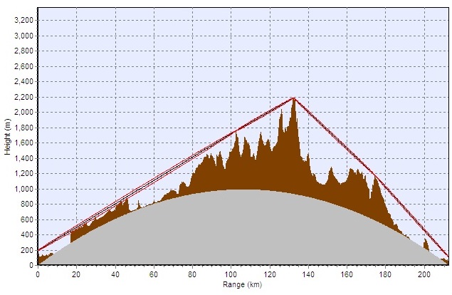
Direct path profile from my QTH to GM3WOJ.
At this point Chris suggested that we could do one better and he would be very happy to host a 3cm personal beacon on either his house or one of his towers provided I built it and set it up. He was happy to keep an eye on it and mind it. I jumped at this and said I was very happy to provide the necessary hardware.
The first itereation - 2014
Over the winter of 2013/14 I assembled the necessary bits and pieces for the first version of the transmitter. The exciter I used one of Andy JNT’s LMX2541 frac-N synthesiser PCBs programmed by a PIC microcontroller to do the keying as per Andy’s recipe. The JT4G keying is timed from GPS. The frequency reference is a well-aged 10 MHz OCXO. It was felt that the extra complications of GPS frequency locking were probably not worth the effort from experience of running the 23 cm beacon GB3EDN
This generated a signal on 3456 MHz which is tripled in frequency (With a bit of recycled Sat TV PCB) to drive a modified QUALCOMM Omnitrak PA (courtesy of Chris Towns, G(M)8BKE). The output is a few hundreds of mW which is fed to a small 35cm BSB dish (remember those?). This gives a beam width of around 7 degrees which from IO77WS gives good coverage of a lot of the UK southwards. The all important housing is from a surplus DMC 22 GHz link unit which had already yielded lots of useful stuff.
![]()
Block Diagram of hardware.
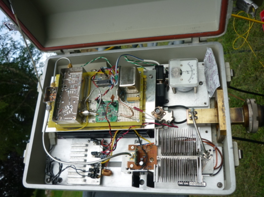
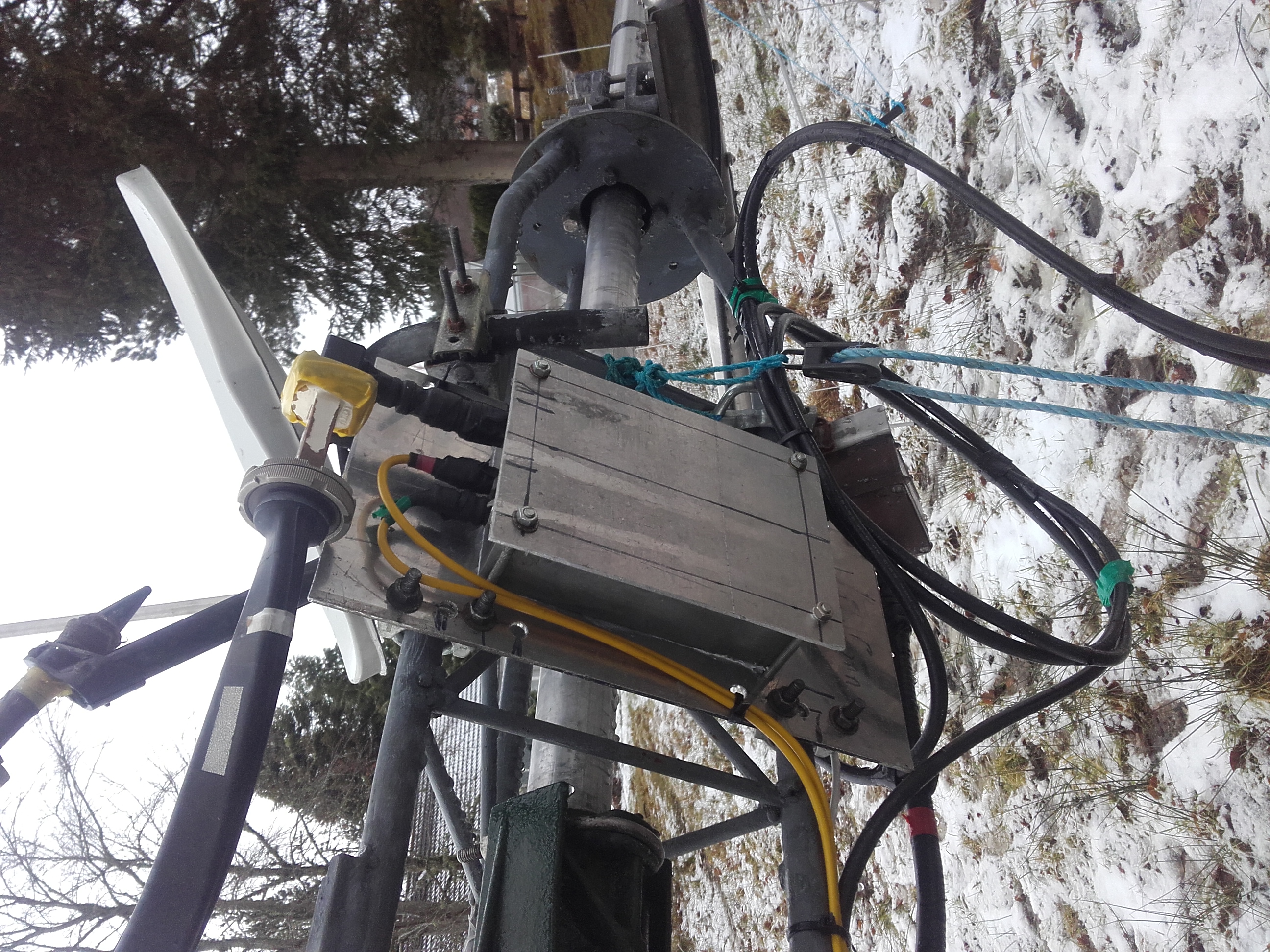
ODU hardware.
After an initial trip to Chris,GM3WOJ’s in mid May to reconnoitre and get some measurements to fix the beacon to one of his smaller towers ( at 11m AGL) I got all the hardware together and tested to my satisfaction. This tower was chosen as it had a clear view south and was not obstructed by trees. It all had to be pretty rugged and weather-proof as I did not want to be driving up and down the A9 to effect repairs. In mid June I returned and between us we installed the beacon. Remarkably all went to plan and we had it on the air within that day. Monitoring the signal locally all sounded good but it remained to be seen if it would get past the mountains to the south which incidentally are the highest in the UK second only to Ben Nevis. An interesting problem was ensuring that the dish was actually pointing in the correct direction when the tower was elevated as there was no received signal to pan it on.
![]()
The beacon hardware with builder.
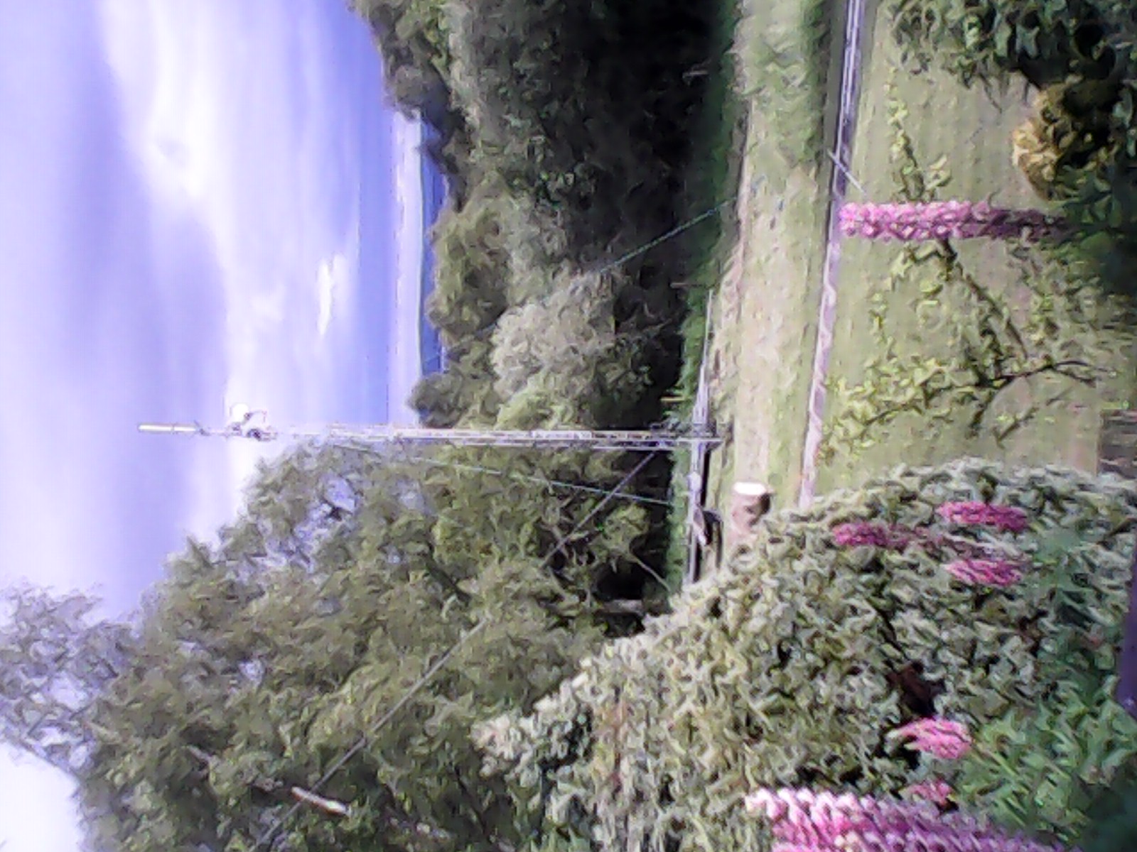
The beacon installed on tower and the take-off south over the Black Isle.
The next day I set off south down the A9 heading home to Edinburgh. I had a Horn antenna fixed to the car as all the best microwave geeks have and monitored it going south. The signal was good on backscatter from the Black Isle but largely disappeared in the vicinity of Inverness. Further down the A9 just before Aviemore where the Cairngorms are in good view from the road it returned and at reasonable strength which was reassuring. I drove up to the Ski slope at Cairngorm and it was not audible LoS as the area is shielded by the direction of the glen. Pointing the antenna at any of the peaks in the vicinity however gave a reassuringly good signal. After that I headed south back on the A9 home with no more signals. It worked with back-scatter but it remained to be seen if forward scatter would work. The next day I was keen to see if it was audible in Edinburgh and I pointed a small (40cm) sat TV dish with a modified LNB as a pre-amp out of my shack window to the north. After a bit of waving it about in the right general direction I was amazed to find the signal was clearly audible at 216 km with an 1800 m obstructed path. The signal was always audible after fixing the antenna to a bracket on the roof.
The Beacon receiver and Internet Audio streaming at GM8PKL's QTH
The Antenna
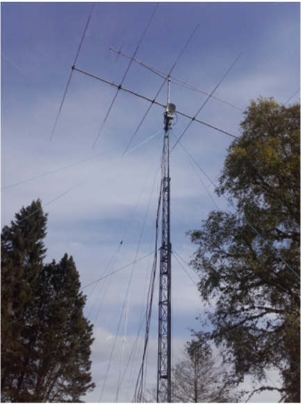
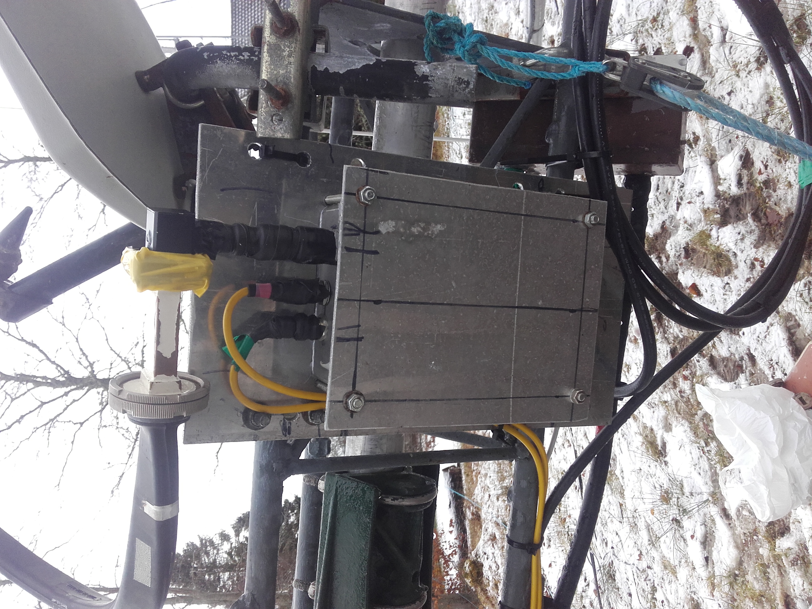
This temporary arrangement worked well until the winter but in January gales the dish was ripped off the roof and landed in the back garden complete with LNB. Very kindly Briain Wilson GM8PKL offered to host the receiver at his QTH which is LoS to some of the grampian peaks. Figures 10 and 11 show the new dish installation. It uses a re-purposed Sky Dish (painted "gorse green" to camoflage it from curious neighbours) and a modified LNB with an external LO feed.
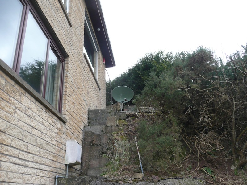
The "Gorse Green" dish. Note it is a good match to the local vegetation!
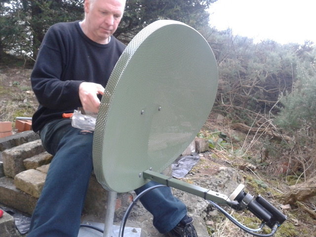
Briain GM8PKL panning the dish.
The LO is locked to the 10 MHz output of a Morion MV89 DOCXO and comes out on a 432 MHz IF. The receiver has to have excellent frequency stability and the Morion reference DOCXO provides this. It sits within 3-4 Hz of 9936 MHz!. These old Morions are amazing It is used to provide the reference frequency for a Chinese ADF4351 demo board. The ADF4351 is programmed by and Arduino Pro-Mini to give an output on 3312 MHz this is amplified and tripled in frequency to 9936 MHz where it is amplified to a level of around 40 mW. The LO generator is housed in Briain's cellar which is adjacent to the dish and LNB but undercover and protected from the elements. The cables are fed to the dish through and air brick and kept as short as possible to minimise losses. As he is on a high spot with a good view over the City of Edinburgh the weather can get quite taxing at times! Pictures of the LO "indoor unit" and a block diagram are below. This also contains the bias Tee for the LNB and the IF take off circuitry for the FT790RII.
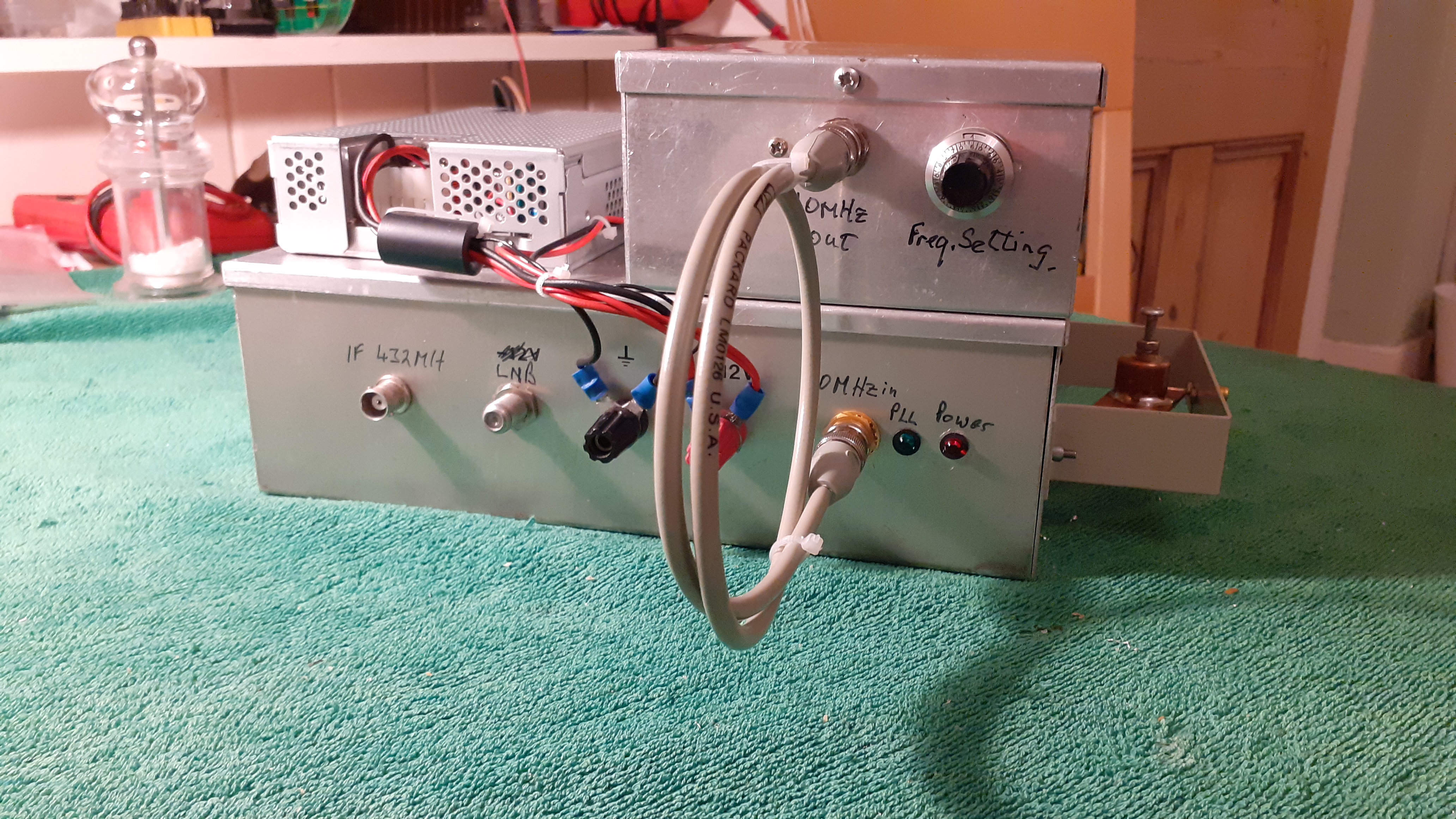
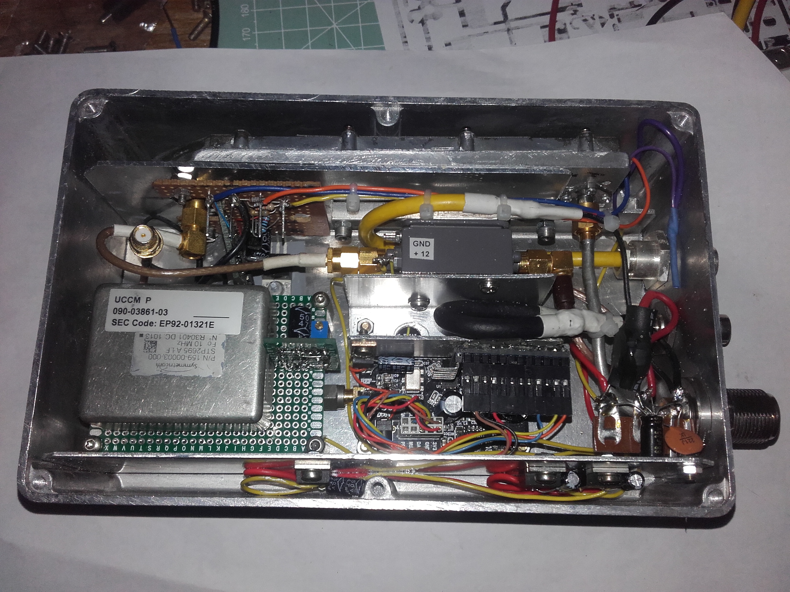
The "indoor" unit.
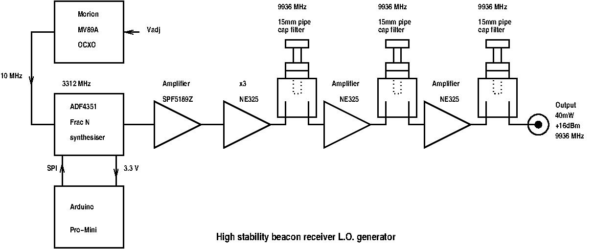
The LO block diagram.
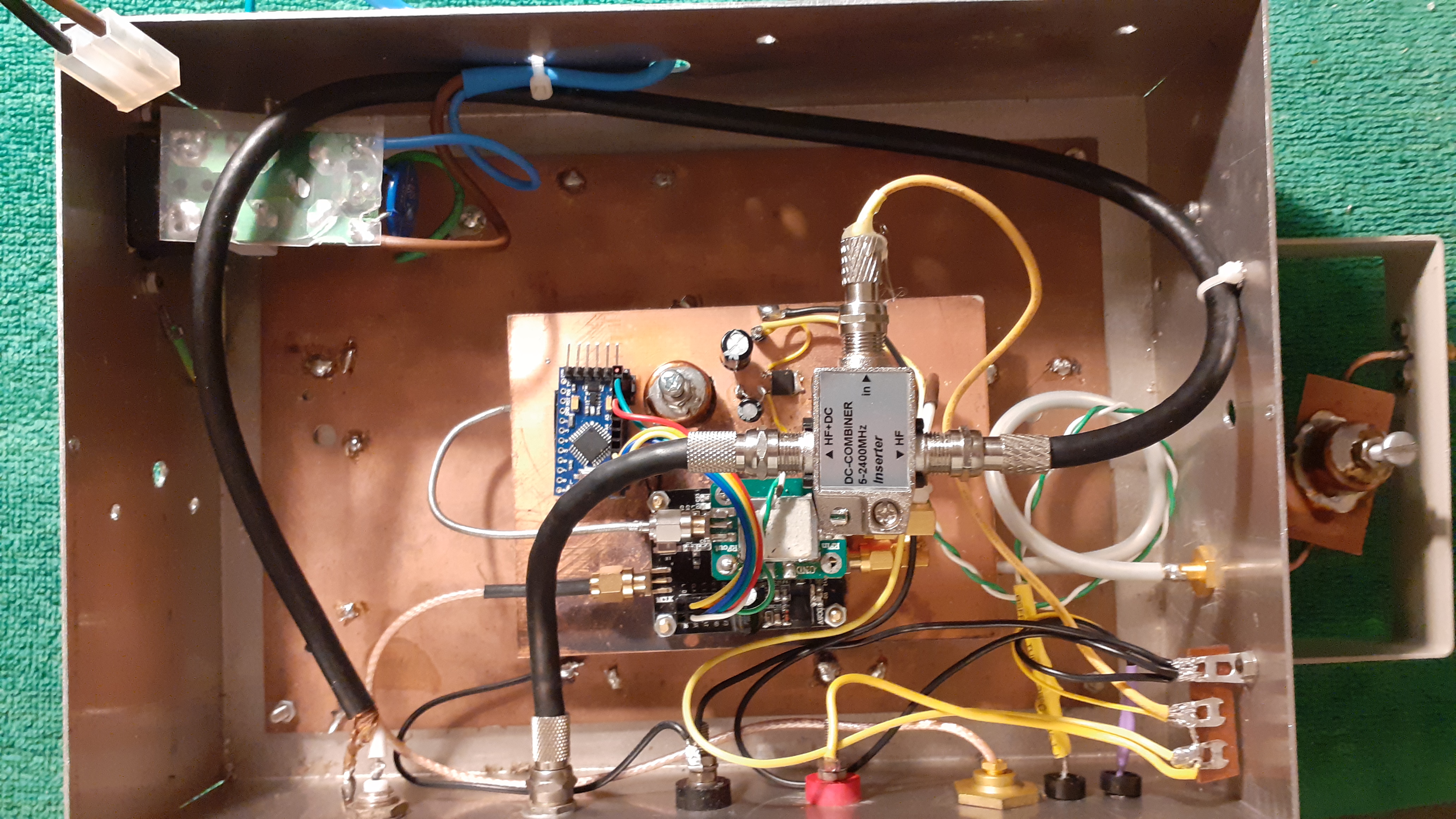
The "entrails" of the indoor unit
The LO signal is fed to the LNB via a length of good quality microwave coax but none-the-less the loss is is in the region of 4-6 dB., hence the high LO level inserted into the coax.
The receiver is a FT790RII which was obtained from Ebay as "Sold for spares" and was a bit of a basket case but I was able to resurrect the Rx side of it and it has proven to be frequency stable and reliable. The audio from the receiver is streamed onto the internet and is at http://gm8.uk:10000/GM3WOJ.m3u and click on “M3U” if it does not open automatically. On a Windows PC the media player will play the steam. On a Linux system VLC is good for playing the stream. On Android any internet radio player will run the stream when the URL is entered. The status of the audio stream can be viewed at https://gm8.uk/beacon .
The stream is generated on a Raspberry Pi 3 single board computer using Darkice, and Icecast is the web-server` programme. These programmes are open-source, and freely downloadable under the GNU GPL licence. They are well established and are in wide use by internet “radio” stations. The audio interface is a USB soundcard.
Viewing the Streaming Audio with Spectran.
The streaming audio can be monitored with Spectran on your PC. To do this you need to install a “virtual audio cable” program to pipe the audio directly from your media player programme output to Spectran. I use the standard Windows media player programme with VB Cable for this purpose. VB Cable is available here at no cost, https://vb-audio.com/Cable/index.htm . Instructions for setting it up are also provided at that URL. To setup Spectran click Setup and then Select soundcard as shown below. Spectran should see the cable input and output as sound card ports.
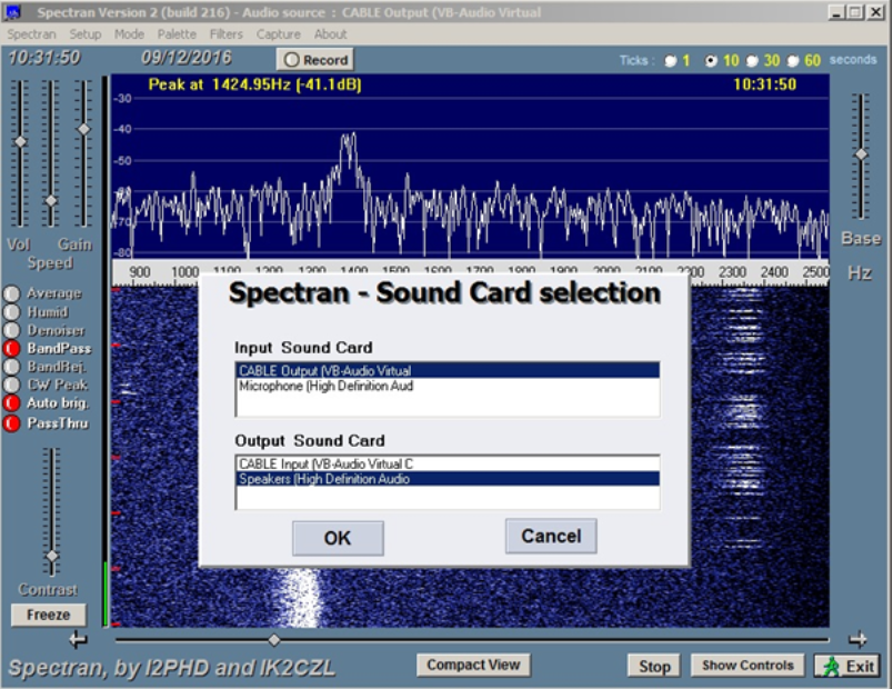
Select Cable Output for the Spectran input sound card and Speakers High Definition Audio as shown and click OK. Start Spectran and you should see the signal on the waterfall display. The plot will lag behind the actual signal because of latency on the internet making it difficult to decode with WSJT software (but it can be done!)
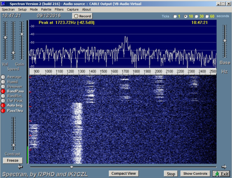
Here a period of carrier, followed by a CW ident, more carrier and the start of the JT4G keying cycle can be seen. As usual the signal is quite dispersed by rainscatter.
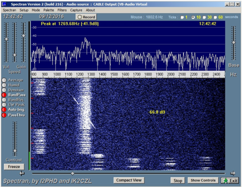
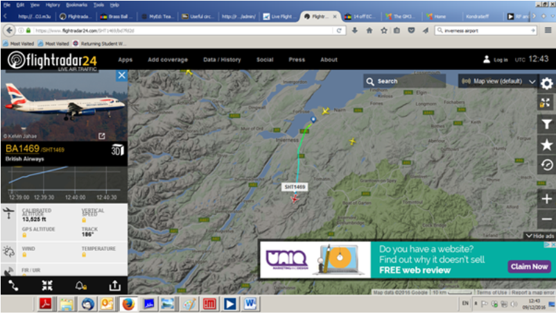
Here is a nice Doppler trace from an aircraft. At the time there was a BA flight leaving Inverness Airport shown below.
The dish on the tower.
Update August 2018
Early in 2018 it was realised that the hardware was unreliable and the beacon had been off the air for considerable periods. A major rethink of the design was carried out and the decision was made to simplify the design to reduce the weight, reduce the complexity and also cut the power consumption.With the earlier addition of GPS frequency locking it had become difficult to power the transmitter because of the voltage drop on the buried low voltage power cable. It was decided to remove the requirement for a GPS frequency locking and GPS timing of the keying. In essence we were going to go back to an old style "steam" beacon that just sent its call sign and QRA. The would allow us to house all of the electronics in an 8 inch by 5 inch by 2 inch Eddystone diecast box. Over the winter of 2017/18 the new hardware was constructed. The frequency reference is a Symmetricom 10 MHz OCXO, the exciter is a Chinese ADF5355 PCB modified to improve its phase noise performance and the PA is a narda X band LNA followed by a Qualcom Omnitracs PA to give 1 watt out. The keying is done using an Arduino Pro-Mini over the SPI bus. The software is based on the OZ2M Arduino beacon keyer modified for cw only. The code was also changed to re-initialise all of the ADF5355 registers every keying cycle instead of just changing the three frequency registers This was done to prevent loss of the output signal if the data in the remaining ten chip registers became corrupted.
![]()
The block diagram of the simplified transmitter.
View of the hardware in the diecast box.
The current drawn by the beacon when the OCXO is warm is around 1.4 Amps. Internal regulators in the box provide stabilised supplies for the internal modules.
Chris did not want any SMPS regulators in the unit as he was concerned about noise being radiated into his HF antennas (it is a nice quiet HF location!) hence the used of linear regulators throughout. A result of this is that the box dissapates around 22 watts of heat (and radiates 1 watt of RF!) and so care had to be taken with the thermal design. To improve cooling the box was mounted on the tower sandwiched between two over size plates of heavy gauge aliminium for cooling. These can be seen below
The cooling plates.
The beacon mounted on the tower showing the cooling/mounting plates.
And finally........
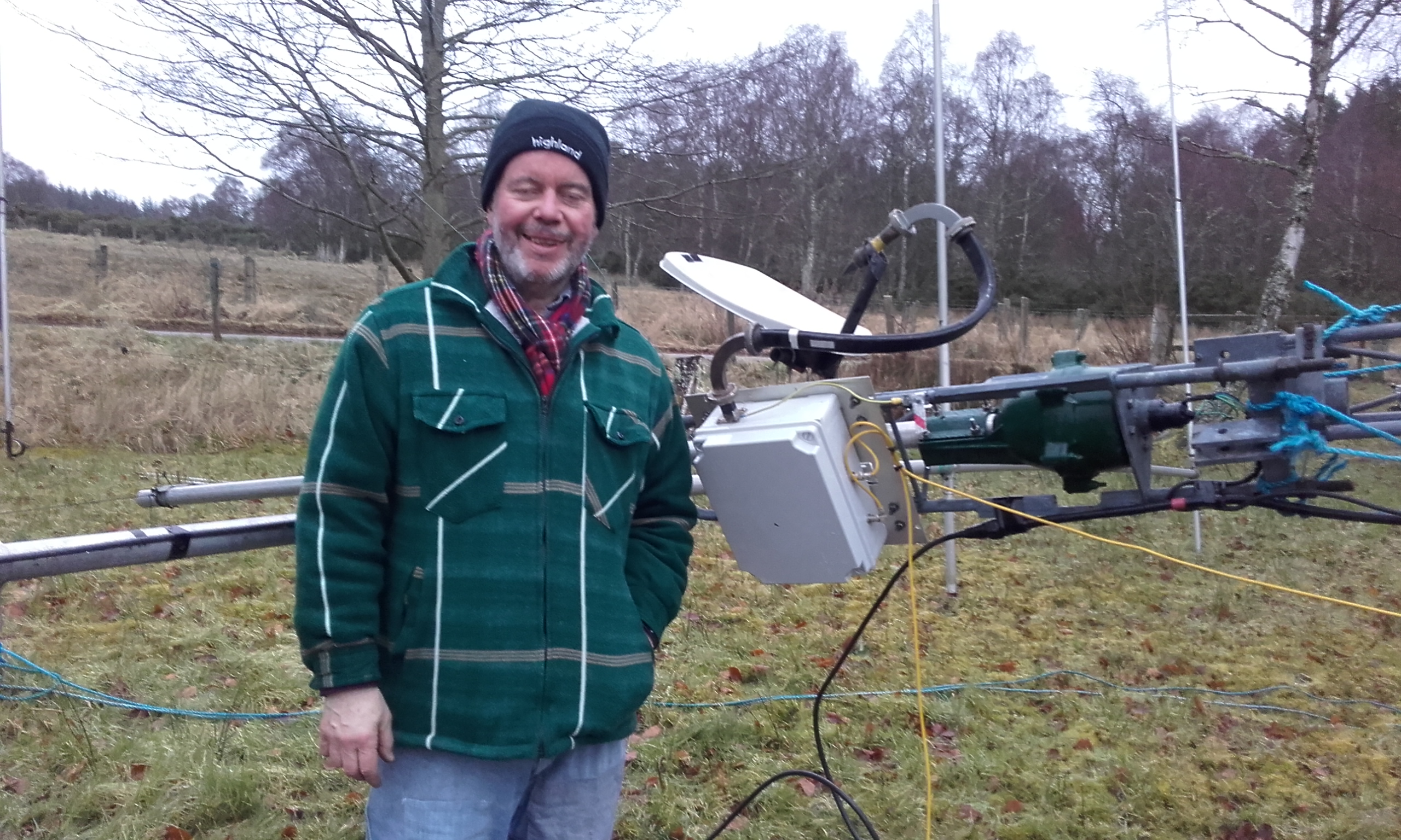
Chris beside an earlier iteration of the hardware.
_________________________________________________________________________________
The vital statistics of the beacon are:
Callsign GM3WOJ
Location IO77WS62
Mode FSK CW
Frequency 10368.400 MHz
Reference OCXO (Usually within 100Hz of nominal carrier frequency)
Power 1 W
Antenna 35 cm off-set parabola (Ex BSB dish)
Beamwidth 7 degrees
Beam heading ~165 degrees
To date the best DX spot is from Tony, G4CBW in IO83UB93, at 537 km with rain-scatter I would expect that it may get further. Up-to-date spots can be viewed at http://www.beaconspot.uk/beaconcm.php?beaconcall=GM3WOJ&bandmhz=10368
Postscript: Needless to say we have not had that QSO yet but we still have plans! That’s the trouble with beacons!
Acknowledgements:
Chris Towns G8BKE – Donation of PA
Chris Tran GM3WOJ – The location.
Briain Wilson GM8PKL- Maintaining the receiver and the management of the audio stream.
Updated: March 2021