Introduction.
The ADF 5355 is a versatile fractional N synthesiser that covers the frequency range 54 MHz to 13.6 Ghz . It uses and on-chip VCO arrangement and is capable of milliHertz frequency resolution at 10 GHz. They are readily available from Chinese vendors on the usual auction sites incorporated into basic development boards. The cost of these boards is comparable with the cost of the chips in one off quantities. For some time I thought that a useful signal generator could be produced based on one of these boards.
In the past I have used them for low powered personal beacons and as local oscillators and signal sources all programmed with Arduinos. Recently I came across the Arduino based signal generator design by Christian Petersen DD7LP based on the ADF4351 [1] and I used his Arduino “sketch” as the starting point for my project. The ADF5355 is capable of operating with frequency steps of milliHertz at 13 GHz, and to have the required arithmetic precision for one Hertz resolution was going to be beyond the capabilities of an 8-bit Arduino ATmega328P. It also has a more complex register structure than the ADF4351. Fortunately there are a number of much more powerful processors supported in the Arduino IDE which are well provideded with libraries and example code.
The ADF5355 gets its very high frequency resolution by two fractional parts to programme its frequency. To have resolutions of the order of Hertz the micro controller must be capable of calculations with around 12 decimal digits which implies a 32 bit controller using double precision arithmetic is required. Details of the register programming are in the datasheet [2].
Microcontroller
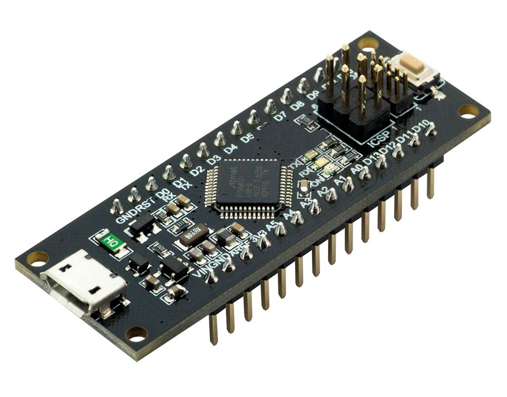
One suitable 32 bit Microcontroller is the WeMOS SAMD21 ARM Cortex M0 which runs at a 48 MHz clock rate. It is supported in the Arduino IDE and if programmed appropriately is capable of the necessary arithmetic precision. It is also available mounted on a pcb with a USB programming interface in the well established Arduino hardware format, Ref [3]. Other options would be some of the Maple Leaf boards using ST Microelectronics STM32 chips.
Display
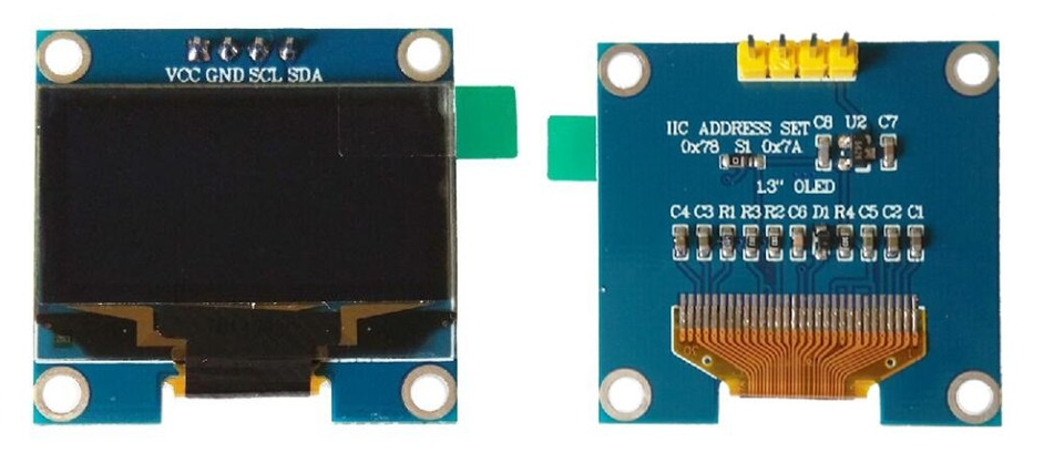
For this project I choose a SSD1306 1.3 inch OLED display. These are available in either I2C or SPI versions. The 0.96 inch variant is more common but requires good eyesight! I sourced the 1.3 inch mounting PCB and the 1.3 inch display separately and assembled my own. Although the display is small it gives a very sharp image. Ref [4] and [5]. I opted for the I2C bus for the display to keep it separate from the SPI bus controlling the ADF5355. I thought this wise to minimise noise transmission to the synthesiser. For a typical schematic of the of the OLED display module see [6].
Rotary encoders
To set the frequency and tuning step size Keyes type push button rotary encoders were used. These are widely available from the usual internet sources.
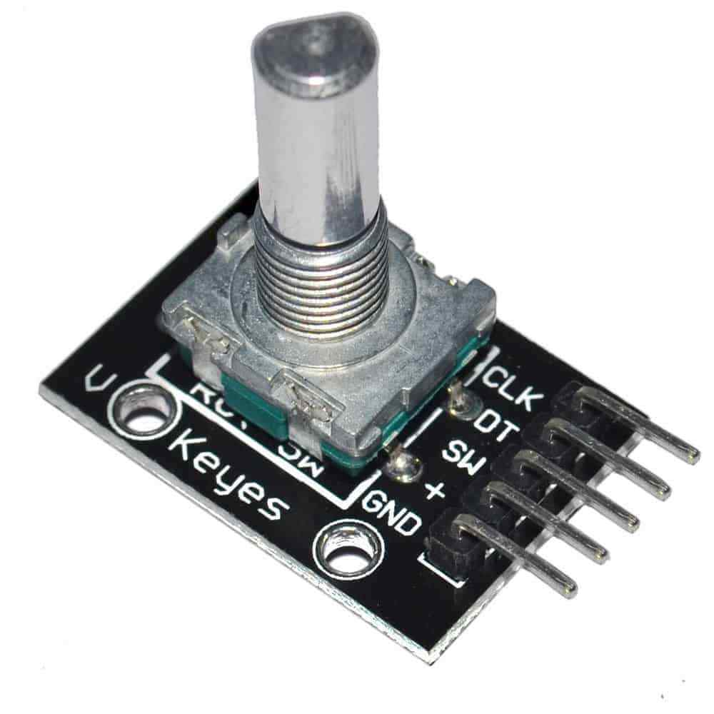
Two encoders were used, one as the main tuning control and the other to select the step size. The push button functions were used to select preset frequencies in each of the amateur VHF/microwave bands and to set the output power level.
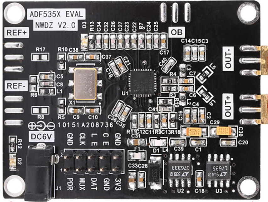
ADF5355 Module
The module I used is shown below. It used a 125 MHz reference oscillator with a push-pull output as that is claimed to improve the phase noise (PN) performance. For this application I used a external 100 MHz ovened reference for better frequency stability and accuracy. To provide a push-pull reference input to the board I supplied the reference via a small trifilar wound bulun transformer constructed using a double hole ferrite, connected to the REF+ and REF- inputs. To disable the onboard reference and connect the external one I had to unsolder L1 and populate R17 and R8 with 100pF capacitors. The schematic is available in the references at the end [7].
The ADF5355 gets its very high frequency resolution by using two fractional parts along with a programmable second modulus to set its frequency, (The first modulus is fixed in hardware). Frac1 is a 24 bit number and Frac2 is a 14 bit number. A good description of the process used to calculate the two fractional parts and the second modulus is given by Andy Talbot G4JNT in [ 2 ]. The Programme calculates these values from the frequency dialed into the OLED display and loads them into the appropriate registers. To have resolutions of the order of Hertz the micro controller must be capable of eleven decimal digits. The SAMD21 is a 32 bit device so when used with double precision arithmetic it is up to the job.
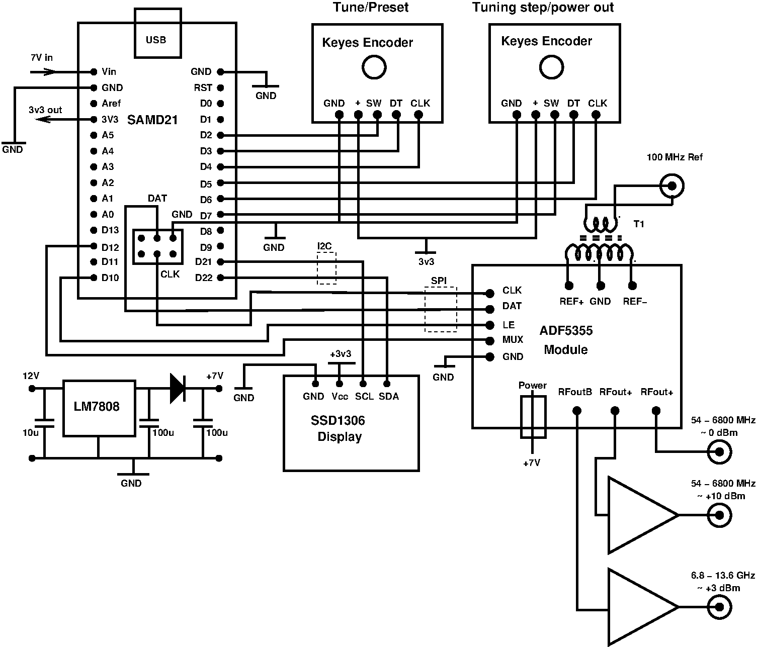
Overall schematic
Arduino code.
The code is available from Github as detailed below. To compile the code and upload it to a SAMD21 board start the IDE running and in the Tools menu select “Arduino/Genuino Zero (Native USB Port)” as the board. It may be necessary to install the software for this if it is not already there. To do this go to Tools > Board > Boards Manager and select “Arduino SAMD21 Boards (32 bits ARM Cortex-M0+)” to install support for the board. The signal generator code can be downloaded from here on Github, [9].
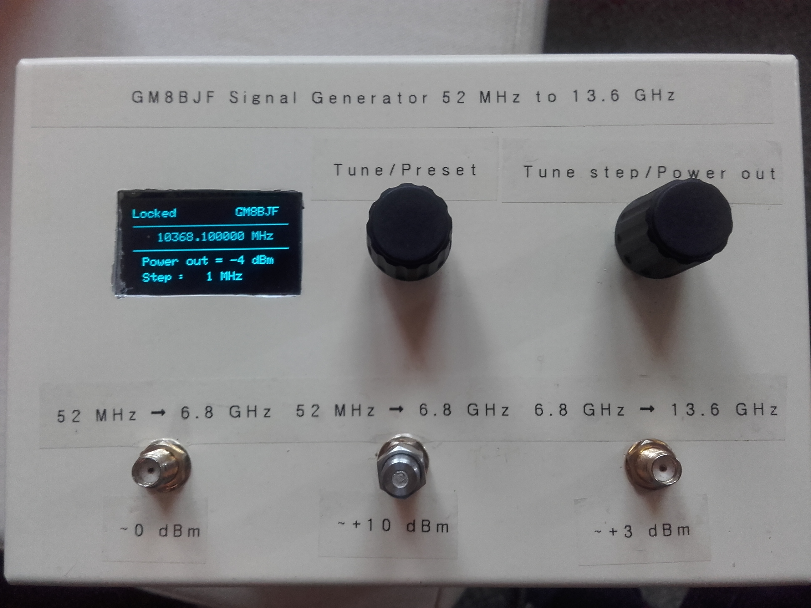
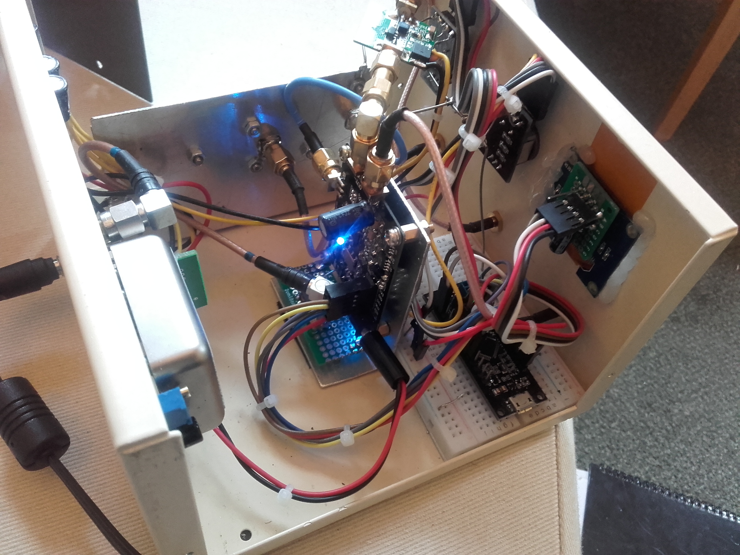
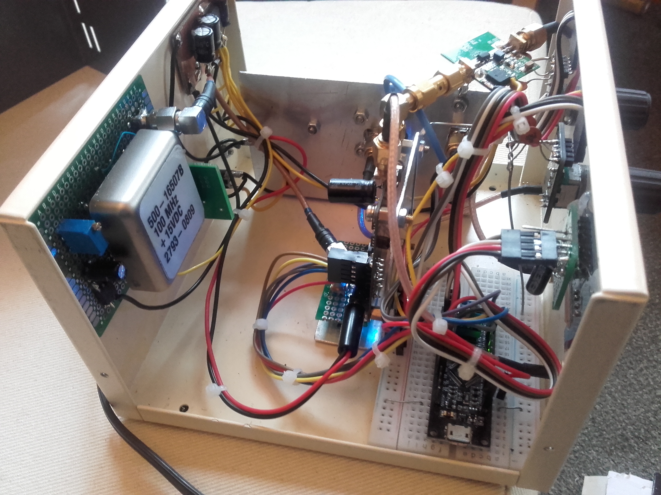
The finished unit
Conclusions
The outcome of this project is a signal generator with continuous coverage between 52 MHz and 13.6 GHz in 10 Hz steps. The step size can be changed in decades from 10 Hz to 1000 MHz. The display is an I2C OLED device which gives a bright well defined image. By adding amplifiers after the outputs from the chip the output power is boosted to useful levels for testing purposes. In terms of phase noise and spurious signal output it is not a match high end professional units but it sure beats then on cost, size and weight!
Brian Flynn
10/06/2019
References:
- http://www.darc-husum.de/Frequenzsynthesizer.html
- https://www.analog.com/media/en/technical-documentation/data-sheets/ADF5355.pdf
- https://www.ebay.co.uk/itm/NEW-WeMos-D1-USB-SAMD21-M0-Mini-ARM-Cortex-M0-32-Bit-extension-For-UNO-Arduino/192669490902?hash=item2cdbff1ed6:g:vUwAAOSwbehbqcTe
- https://www.aliexpress.com/item/1-3-inch-30P-White-Blue-SPI-OLED-Screen-SSD1306-Drive-IC-128-64-Parallel-I2C/32813434220.html?spm=a2g0s.9042311.0.0.17f54c4dBcL1BS
- https://www.aliexpress.com/item/SPI-IIC-Adapter-Board-for-1-3-inch-OLED-Screen-2-8-5-5V/32248690998.html?spm=a2g0s.9042311.0.0.17f54c4dBcL1BS
- http://wiki.sunfounder.cc/index.php?title=OLED-SSD1306_Module
- http://gm8bjf.joomla.com/images/pdf/ADF5355_sch.pdf
- http://www.g4jnt.com/ADF5355_Synthesizer_Control.pdf
- https://github.com/gm8bjf/ADF5355_sig_gen
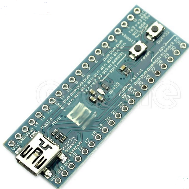
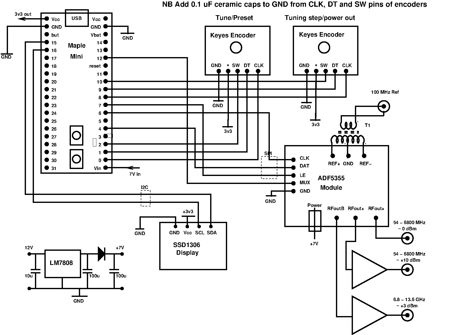
Addendum 1 - Using a Maple Mini Microcontroller instead of the SAMD21
Initial work on this project was done with the WeMOS SAMD21 board. This board is relatively expensive at around £8. A lower cost alternative is a Maple Mini board. These are around £3 and sport a 32-bit STmicroelectronics STM32F103CB ARM Cortex-M3 128k Flash, 20k RAM processor and are very adequate for this project. The pinning is different from the Atmel SAMD21 and there are slight differences in the code and the schematic. The code for the Maple Mini is available at [9] and the schematic showing the connections is below.